Purpose and audience. This operations manual describes the OPC Bridge completely – from the fundamentals of the supported fieldbus and network protocols through installation and configuration to operation, maintenance and troubleshooting. It is written for commissioning engineers, automation technicians, IT/OT administrators and maintenance staff alike. Every technical term is explained on first use; the fundamentals chapters assume no prior knowledge. Advanced readers may skip the fundamentals and go straight to the configuration chapters.
Language versions. This document is available in English and German. The German version is Deutsche Fassung.
Conventions. Monospace denotes input, addresses, file names and code. Italics denote controls and technical terms. Boxes marked »Note«, »Caution« and »Tip« highlight important points.
Part I – Fundamentals
1. Introduction and overview
1.1 What is the OPC Bridge?
The OPC Bridge is a universal protocol converter for industrial communication. In a typical plant, many devices and systems speak different "languages" – so-called protocols:
- an older machine controller provides values via OPC-DA,
- an energy or flow meter communicates over Modbus,
- a modern sensor sends via MQTT to a cloud,
- a diesel generator or vehicle delivers data over the CAN bus,
- the supervisory control system expects OPC-UA.
For these devices to work together, their values must be translated from one protocol into another. That is exactly what the OPC Bridge does: it connects to several sources and targets at the same time and transfers values between them – in both directions.
1.2 The interpreter analogy
Picture a round table with people from different countries. Each speaks only their own language. In the middle sits an interpreter who takes each statement and passes it on to the others in their respective language.
The OPC Bridge is that interpreter. As the user you only need to define two things:
- Who is at the table? – these are the connections (e.g. "the Modbus PLC", "the OPC-UA control system").
- Who should tell what to whom? – these are the mappings (e.g. "the PLC's temperature → the control system's temperature").
Everything else – constant polling, conversion, buffering on faults and forwarding – the Bridge handles automatically.
1.3 Feature overview
| Area | Features |
|---|---|
| Protocols | OPC-DA (client), OPC-UA (client and server), Siemens S7 (direct), Modbus TCP/RTU (master and slave), MQTT, MQTT Sparkplug B, SQL/ODBC, InfluxDB, CAN (incl. J1939), REST/Webhook, Simulator |
| Data flow | Bidirectional routing (A→B, B→A, ↔), merging of multiple sources, multithreading |
| Real-time | Live values over WebSocket with polling fallback |
| Throughput | Batch/bulk writing (SQL multi-row, JSON-array webhook, InfluxDB line protocol) |
| Conversion | Factor/offset, free formulas, type and byte-order conversion |
| Virtual sources | Computed points, redundancy/hot-standby |
| Reliability | Persistent store-and-forward (SQLite), automatic reconnection |
| OT→IT coupling | Bridge-Link: outbound TLS tunnel without inbound firewall ports, optional strict one-way / data-diode mode |
| Monitoring | History, trends, alarm rules (e-mail/webhook), OPC-UA A&E |
| Sharing | WebView – token-protected read-only live view |
| REST API | Complete API with built-in OpenAPI documentation (offline) |
| Security | Configurable API authentication, roles, HTTPS, OPC-UA security, LDAP/Active Directory, OIDC/SSO, TOTP 2FA |
| Interface | Multilingual (German, English, French, Spanish, Portuguese) |
| Copy protection | Machine-bound signed serial numbers (Ed25519), demo mode |
| Delivery | Windows setup (.exe), Debian package (.deb), Docker image |
1.4 Typical use cases
- Modernization: connect a legacy OPC-DA plant to a new OPC-UA control system without replacing the controller.
- Digitalization/IIoT: deliver values from Modbus meters to an MQTT cloud or a Unified Namespace (Sparkplug B).
- Vehicle/generator integration: provide CAN signals of a generator set as OPC-UA or Modbus values.
- Secure OT/IT coupling: transport values from production through a DMZ into IT without opening the production firewall.
- Protocol bridge Modbus↔OPC: let an OPC-UA client access Modbus registers.
2. System architecture
2.1 Component model
Internally the OPC Bridge consists of several cooperating layers:
- Drivers: there is one driver per protocol. It handles connecting, polling, writing and reporting values. Each connection in the UI is an instance of a driver.
- Engine: the core. It manages all drivers, executes the mappings (forwards values), applies formulas, buffers on faults (store-and-forward) and writes the history.
- Virtual sources: computed points and redundancy groups that derive new values from existing ones.
- Notifier: evaluates alarm rules and sends e-mails/webhooks.
- Web interface and REST API: operation and integration via browser or programs.
2.2 Data flow
A value typically travels this path:
- The source driver reads the value from the device (or receives it) and reports it to the engine with address, value, quality and timestamp.
- The engine finds all mappings in which this point is the source.
- For each mapping the formula is applied (if configured) and the data type converted.
- The value is handed to the target driver. If the target is unreachable and store-and-forward is active, the value is buffered.
- The target driver writes the value to the device (or publishes it).
At the same time the value may be written to the history, checked against alarm rules, and pushed to the live view (via WebSocket).
2.3 Operating model
The Bridge runs as a service (Windows service, systemd service or Docker container) in the background – regardless of whether a browser is open. The web interface is only the operation and monitoring tool; the actual data exchange runs inside the service.
»Note« The Bridge keeps working even when no browser is connected. Closing the browser does not stop data transfer.
3. Basic terms
The following terms are used throughout this manual.
| Term | Meaning |
|---|---|
| Connection | A link to a device or system. Has a type (= protocol) and its own settings. |
| Driver | The software behind a connection type (e.g. the Modbus driver). |
| Point / Tag | A single value within a connection (e.g. a temperature). |
| Address | Identifies the location/name of a point in the device (e.g. HR100 or ns=2;s=Temp). |
| Mapping | Rule "source A → target B". Defines which point is transferred to which. |
| Direction | A→B, B→A or A↔B (bidirectional). |
| Quality | Goodness of a value: good, uncertain, bad. |
| Timestamp | The time at which the value was valid. |
| Master / Slave | Modbus roles: master polls, slave answers/provides values. |
| Client / Server | The client connects to the server. The Bridge can be either, depending on the protocol. |
| Publish / Subscribe | MQTT principle: publishing or subscribing to topics. |
| OT / IT / DMZ | Production network / office network / isolated intermediate zone. |
| Engine | The internal core that executes mappings. |
| Store-and-forward | Buffering values when a target is offline. |
| Virtual source | Computed point or redundancy group. |
4. Protocol fundamentals in detail
This chapter explains every supported protocol from the ground up: what it is for, how it is built, what a message actually looks like, and what to watch out for during configuration. Read only the sections relevant to your plant.
4.1 About industrial communication
Automation is roughly divided into two worlds:
- Field level (OT, Operational Technology): sensors, actuators, controllers (PLC). Here real-time behaviour, robustness and simple, lean protocols matter (Modbus, CAN).
- Supervisory/enterprise level (IT): SCADA, MES, ERP, cloud. Here security, structure and interoperability matter (OPC-UA, MQTT, REST).
Protocols can be grouped by their communication pattern:
| Pattern | Explanation | Examples |
|---|---|---|
| Polling | One party actively requests values, the other answers. | Modbus master, OPC-UA client (read) |
| Subscription | The server only sends on change. | OPC-UA subscription |
| Publish/Subscribe | Senders publish, receivers subscribe – decoupled via a broker. | MQTT, Sparkplug B |
| Broadcast/bus | All participants listen; messages carry an ID. | CAN |
The OPC Bridge handles all of these patterns at once and translates between them.
A recurring theme is the representation of numbers: depending on the protocol, values are transferred as single bits, as 16-bit registers, as 32-bit floating-point numbers or as bit fields in messages. Section 4.12 covers data types and byte order centrally, because this is the most common source of error during commissioning.
4.2 OPC-DA (Classic)
Origin and purpose. OPC (originally OLE for Process Control) emerged from 1996 to standardize data exchange between Windows automation software and controllers. OPC-DA (Data Access) is its most widely used part – practically every older SCADA system and Windows driver software offers an OPC-DA server. Millions of OPC-DA interfaces are still in use in legacy plants.
Technical structure. OPC-DA is based on Microsoft's component model COM and – across machine boundaries – DCOM. A server's data is organized hierarchically:
OPC-DA server
 └─ Group (e.g. "Line1")
     └─ Item  (e.g. "Channel1.Device1.Tag1")  → value + quality + timestamp
An item is a single data point. Each item has an ItemID (the address, e.g. Channel1.Device1.Temperature), a value, a quality (good/uncertain/bad) and a timestamp.
The OPC Bridge acts as an OPC-DA client: it connects to a local or remote DA server (via its ProgID such as Matrikon.OPC.Simulation), creates a group and reads or writes items.
Address format. Channel1.Device1.Tag1 – the exact notation is defined by the server. The Bridge can browse the server's address tree.
Pitfalls.
- OPC-DA runs only on Windows (COM/DCOM dependency).
- Remote access (DCOM) is notoriously hard to configure. Recommendation: run the Bridge and DA server on the same machine – then DCOM is not needed at all.
- The bitness (32/64-bit) of the Bridge must match the installed OPC Core Components wrapper.
»Tip« Modernizing an OPC-DA plant usually means: read OPC-DA → provide as OPC-UA. Create an OPC-DA connection (source) and an OPC-UA server connection (target), then link the points via mappings.
4.3 OPC-UA
Origin and purpose. OPC-UA (Unified Architecture, from 2008) is the modern successor to OPC-DA. It solves its main problems: it is platform-independent (Windows, Linux, controllers, cloud), secure (encryption, signing, certificates, user authentication) and self-describing (a client can explore the address space and read data types). OPC-UA is today's de-facto standard for connecting control systems (IEC 62541).
Technical structure. OPC-UA data lives in an address space of nodes. Each node has:
- a NodeId – the unique address, consisting of a namespace index (
ns=) and an identifier, which is either- a string (
s=), e.g.ns=2;s=Line1.Temperature, or - a number (
i=), e.g.ns=3;i=1001,
- a string (
- a BrowseName and DisplayName (readable labels),
- a node class (variable, object, method …),
- for variables: a value with data type, quality (StatusCode) and timestamp.
The namespace index separates different "namespaces": ns=0 is OPC-UA's own standard space; ns=2, ns=3 … are vendor-specific spaces.
Two operating modes in the Bridge.
- OPC-UA client: the Bridge connects to a foreign server (endpoint URL such as
opc.tcp://192.168.0.10:4840) and reads/writes nodes. It can also create subscriptions (server reports only changes) and subscribe to Alarms & Events (A&E). - OPC-UA server: the Bridge provides its own server (default port 4840). Other systems connect and read the provided values. The path you assign,
Plant/Line1/Temperature, is automatically turned into a NodeId.
Security. OPC-UA has security policies defining signing and encryption:
| Policy | Meaning |
|---|---|
None | no protection (protected networks only) |
Basic256Sha256 | signing/encryption (common standard) |
Aes128_Sha256_RsaOaep, Aes256_Sha256_RsaPss | modern policies |
Plus the MessageSecurityMode: None, Sign (signed only) or SignAndEncrypt (signed and encrypted). Partners exchange certificates and must trust each other.
Alarms & Events (A&E). A UA server can deliver not only values but also events (alarms, state changes). The Bridge's UA client can subscribe to these – filtered by source, event type and minimum severity.
»Note« Because OPC-UA is self-describing, browsing is especially powerful here: the Bridge can traverse the server's entire address space and bulk-create points via the wizard.
4.4 Modbus TCP and RTU
Origin and purpose. Modbus (1979, Modicon) is one of the oldest and simplest industrial protocols – and precisely for that reason extremely widespread: PLCs, energy and heat meters, drives, inverters, sensors and actuators almost always offer Modbus. Its simplicity makes it robust and easy to diagnose.
Variants.
- Modbus RTU: over a serial line (RS-485 or RS-232). Several devices on one bus, each with a device address (unit ID) 1…247. Binary transmission with CRC check.
- Modbus TCP: over Ethernet/IP (default port 502). Same logic but as a TCP packet; the unit ID is carried along (relevant with gateways to serial devices).
Data model. Modbus has exactly four data areas:
| Area | Code | Width | Content | Access |
|---|---|---|---|---|
| Coils | CO | 1 bit | switch outputs | read + write |
| Discrete Inputs | DI | 1 bit | digital inputs | read only |
| Input Registers | IR | 16 bit | measured values | read only |
| Holding Registers | HR | 16 bit | setpoint/parameter values | read + write |
Each area is numbered (address 0, 1, 2 …). In older Modicon notation the area is encoded by the number range: 0xxxx = coils, 1xxxx = discrete inputs, 3xxxx = input registers, 4xxxx = holding registers (e.g. 40001 = first holding register). The Bridge understands both notations.
Message structure (simplified). A Modbus request "read 2 holding registers from address 100 of device 1" consists of:
[Unit ID=01] [Function=03 (Read Holding Registers)] [Start=00 64] [Count=00 02]The response contains the byte count and the register contents:
[Unit ID=01] [Function=03] [Byte count=04] [Reg100=41 20] [Reg101=00 00]Numbers across multiple registers. A register holds only 16 bits (0…65535). Larger values combine several registers:
- 32-bit integer (
int32/uint32) or 32-bit float (float32): 2 registers. - 64-bit (
int64/double): 4 registers. - Text (
string): several registers, 2 characters each.
The byte order is crucial here – see section 4.12 and the register inspector (chapter 33), which shows all interpretations at once.
Roles in the Bridge. For TCP and RTU the Bridge can be:
- Master (client): actively polls registers from a device and writes them.
- Slave (server): provides its own registers that other masters can poll. This lets the Bridge, for example, expose OPC-UA values as Modbus registers "outward".
Address format in the Bridge. [Unit:]Area Offset[.Bit][:Type[:ByteOrder]]
Examples: HR100:float32, 2:IR10:int32:CDAB, CO5, HR7.3 (bit 3 of a register), 40001:uint16, HR200:string20.
4.5 MQTT
Origin and purpose. MQTT (Message Queuing Telemetry Transport, 1999, originally for pipeline telemetry) is the standard protocol of the Internet of Things. It is extremely lean and optimized for unreliable, low-bandwidth networks (cellular, satellite). Ideal for connecting many distributed devices to a central place.
Communication pattern: publish/subscribe. Unlike Modbus, nobody polls directly. Instead there is a central broker (server). Devices publish values under a topic, and interested parties subscribe to that topic:
Sensor --publish "hall1/temp" = 21.4--> [ Broker ] --deliver--> subscriber(s)Advantage: sender and receiver do not know each other and need not be online at the same time – they are decoupled via the broker.
Topics. A topic is a hierarchical path with / as separator, e.g. plant/hall1/line3/temperature. Wildcards are possible when subscribing (+ for one level, # for all remaining).
Payload. The message content is free – often a number, frequently JSON, e.g. {"temp": 21.4, "unit": "C"}. The Bridge can extract a specific value from the JSON by appending a JSON path with @: sensor/abc@data.temperature.
Quality of Service (QoS). MQTT has three delivery guarantees: QoS 0 (at most once), QoS 1 (at least once), QoS 2 (exactly once). Higher QoS = safer but more overhead.
Retained messages & last will. A retained message is stored by the broker so new subscribers immediately receive the last value. The last will is a message the broker sends automatically if a device loses its connection unexpectedly.
Address format in the Bridge. hall1/temp or with JSON path sensor/abc@data.temperature.
4.6 MQTT Sparkplug B
The problem Sparkplug solves. "Bare" MQTT defines no structure: every vendor names topics differently and encodes payloads differently. In large plants this leads to chaos. Sparkplug B is an open specification on top of MQTT that prescribes topic structure, payload format (Google Protocol Buffers) and a fixed lifecycle. This creates a Unified Namespace (UNS) – a consistent, searchable real-time model of the entire plant. Sparkplug B is supported by Ignition, HiveMQ, AVEVA and many IIoT platforms.
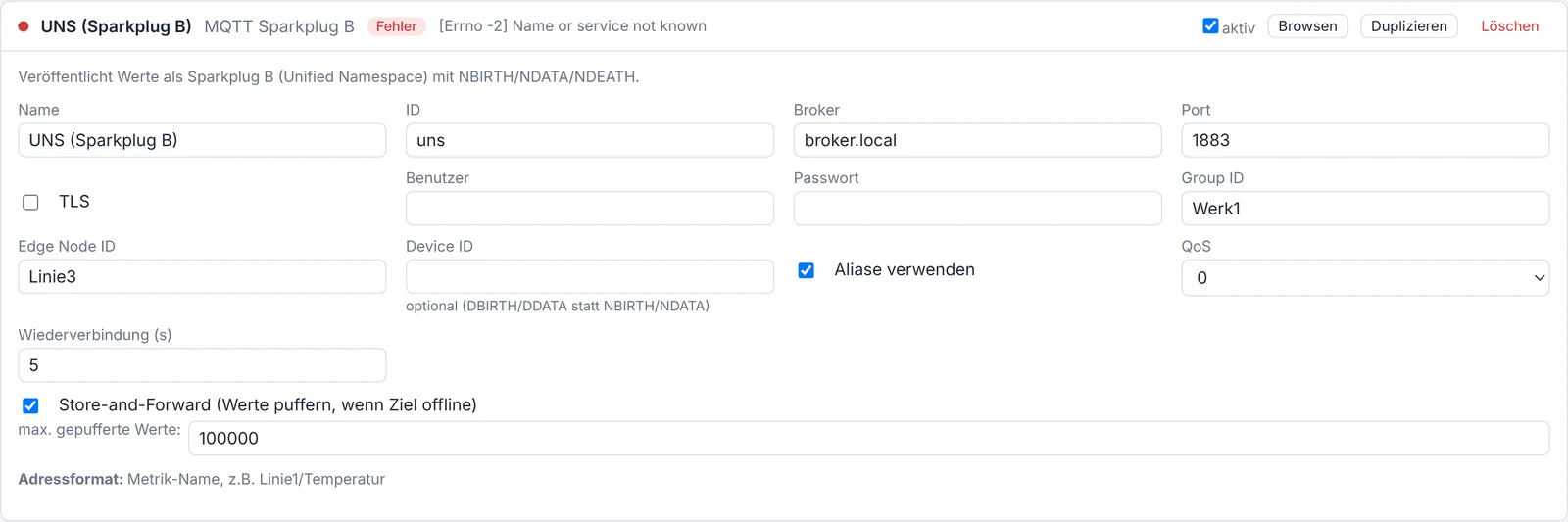
Roles. Sparkplug has edge nodes (data sources at the plant edge) and host applications (e.g. SCADA). The OPC Bridge acts as an edge node.
Topic structure. spBv1.0/<GroupID>/<MessageType>/<EdgeNodeID>, e.g. spBv1.0/Plant1/NDATA/Line3.
Lifecycle (the heart of it).
| Message | Meaning |
|---|---|
| NBIRTH (Node Birth) | On connect, the node announces all its metrics with name, data type and a short alias number. Contains bdSeq (birth/death counter). |
| NDATA (Node Data) | Afterwards, changes are sent using only the alias number (without the long name) – saving bandwidth significantly. |
| NDEATH (Node Death) | The "death certificate" registered as the last will. If the node fails, the broker sends it automatically – all subscribers immediately know the data is stale. |
| NCMD (Node Command) | Commands to the node, including Rebirth (request a new birth message) and write values. |
Each message carries an incrementing sequence number (seq); gaps indicate loss. The combination of bdSeq and seq makes the data stream traceable.
What the Bridge does.
- Sends NBIRTH on connect with all write points as metrics (including aliases and
Node Control/Rebirth). - Sends changes as NDATA (alias + value + sequence only).
- Registers NDEATH as the last will.
- Answers Rebirth requests and writes NCMD values back into the plant (bidirectional).
Data type mapping. Generic types are mapped automatically to Sparkplug types (Int8/16/32/64, UInt…, Float, Double, Boolean, String).
4.7 CAN bus
Origin and purpose. CAN (Controller Area Network, Bosch, 1986) is the dominant bus in vehicles, construction machinery, generators, medical and industrial equipment. It is robust, real-time capable and needs only two wires. The bus carries many small messages (frames) that all participants listen to.
Frame structure. A CAN data frame essentially contains:
| Field | Size | Meaning |
|---|---|---|
| Identifier (ID) | 11 bit (standard) or 29 bit (extended) | identifies the message and its priority (lower ID = higher priority) |
| DLC | 4 bit | number of data bytes (0…8) |
| Data | 0…8 bytes | the actual payload |
| CRC | 15 bit | checksum |
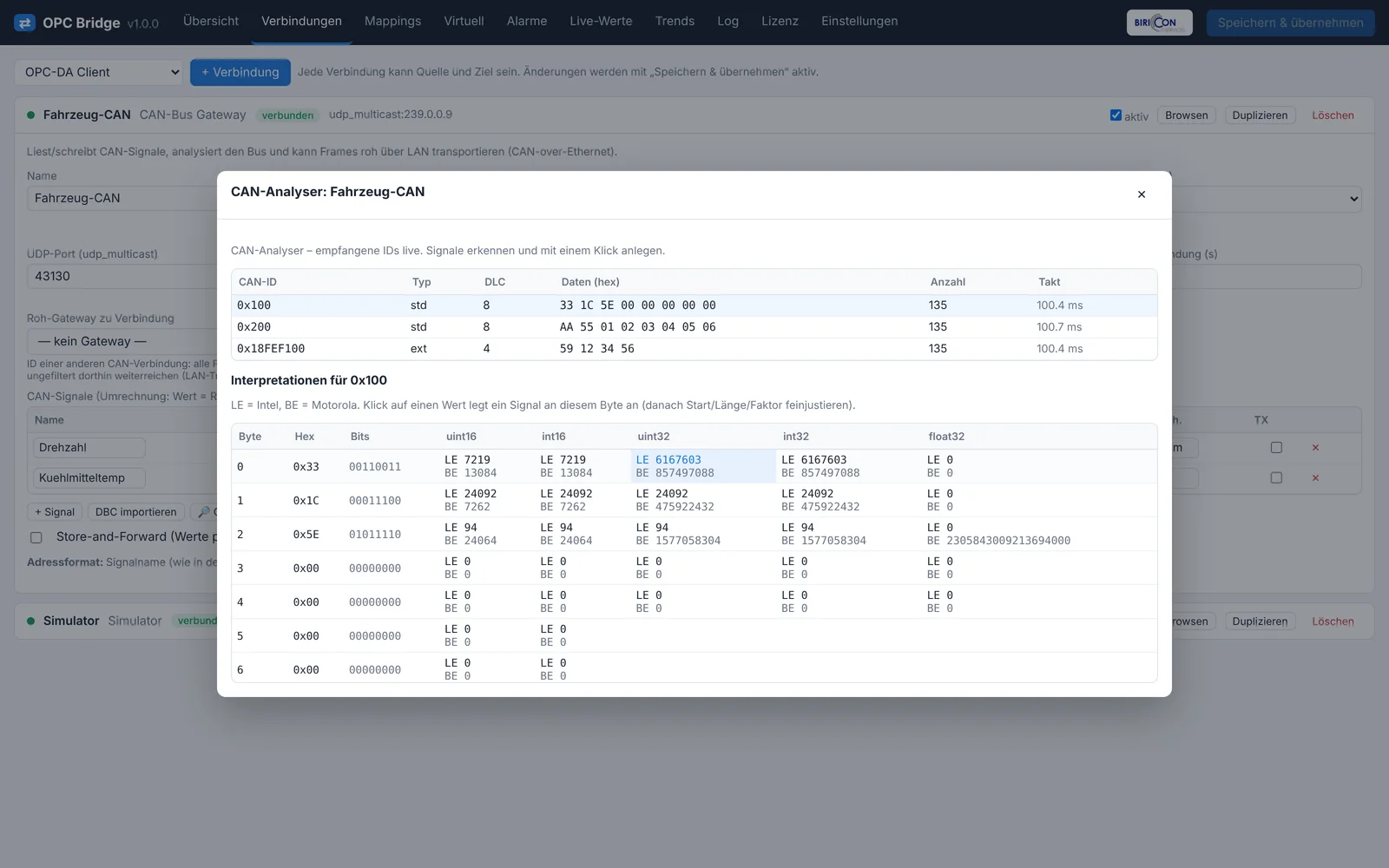
Importantly, CAN transmits no signal names. The actual values (signals) sit as bit fields in the up to 8 data bytes. Which bit is which signal, with which length, factor and offset, is defined either
- in a DBC file (the standard description format; the Bridge can import DBC), or
- must be determined with the Bridge's CAN analyzer (listen, recognize patterns).
Signal definition. A signal is described by: start bit, length (bits), byte order (Intel/little or Motorola/big), sign, factor and offset. The physical value is raw * factor + offset. Example: a 16-bit raw value with factor 0.1 and offset −40 gives, for raw value 850, the value 850*0.1−40 = 45.0 °C.
Interfaces. The Bridge speaks CAN over various hardware/transports: SocketCAN (Linux), UDP multicast (CAN-over-Ethernet), slcan (serial CAN adapters), PCAN (Peak), Kvaser, Vector and a virtual bus for testing.
Two operating modes.
- Signal extraction: extract signals from frames, convert via factor/offset and export to OPC/Modbus/MQTT.
- Raw gateway: transport the entire bus unfiltered over LAN (CAN-over-Ethernet), e.g. to couple two remote CAN segments over Ethernet.
4.8 J1939
Purpose. SAE J1939 is a CAN-based standard for commercial vehicles, engines and generator sets (diesel generators, construction and agricultural machinery). It defines how the 29-bit ID and the data bytes are structured so that devices from different vendors interoperate.
Structure of the 29-bit ID. The extended ID is structured into:
| Part | Meaning |
|---|---|
| Priority | 3 bit – bus priority |
| PGN (Parameter Group Number) | identifies the kind of message (e.g. "engine speed") |
| SA (Source Address) | address of the sending device |
The PGN points, in the J1939 specification, to a fixed list of SPNs (Suspect Parameter Numbers) – the individual measured values in the data bytes. Example: PGN 61444 (EEC1) contains the engine speed among others.
What the Bridge does. The CAN analyzer detects extended frames and automatically decodes PGN, SA, priority and destination address and displays them. This makes it quick to identify J1939 messages without a DBC.
4.9 SQL / ODBC
Purpose. Process values often need to be written to a relational database (logging, reporting) or setpoints read from one. Supported databases include Microsoft SQL Server, PostgreSQL, MySQL/MariaDB and SQLite.
Structure. The Bridge uses a database abstraction layer (SQLAlchemy, optionally ODBC). You configure:
- a read query (SELECT) delivering address and value, and/or
- a write statement (INSERT/UPDATE) with placeholders
:addr,:value,:ts.
Thus each forwarded value is stored or read as a record. Intervals and connection parameters (connection string) are configurable.
4.10 REST / Webhook
Purpose. To send values to arbitrary web services, low-code platforms, cloud endpoints or custom microservices.
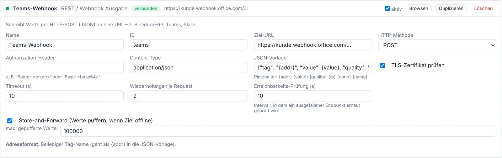
Structure. For each value to forward, the Bridge sends an HTTP POST request to a configured URL. The body is a freely definable JSON template with placeholders:
| Placeholder | Content |
|---|---|
{addr} | point address |
{value} | value |
{quality} | quality |
{ts} | timestamp (ISO-8601) |
{conn} | connection ID |
{name} | connection name |
Example template: {"tag":"{addr}","v":{value},"q":"{quality}","t":"{ts}"}.
Combined with store-and-forward, no values are lost when the endpoint is temporarily unreachable.
4.11 Bridge-Link (OT→IT tunnel)
The security problem. In a properly segmented plant (Purdue model), no connection from outside may enter the production network (OT). Firewalls allow only outbound connections. Yet process values must reach the IT/DMZ zone.
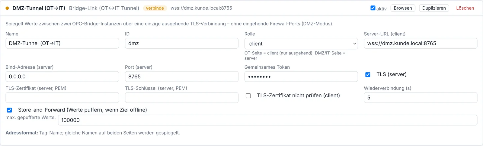
The solution. Two OPC Bridge instances are coupled via the Bridge-Link:
- The OT side runs as a client and establishes the connection outbound only – a single, TLS-encrypted connection to the DMZ.
- The IT/DMZ side runs as a server and accepts this connection.
- Values with the same tag name are mirrored in both directions.
No inbound port needs to be opened in the OT firewall. A shared token secures the coupling; store-and-forward on the OT side buffers on connection loss.
4.12 Data types and byte order
This is the most important practical fundamental, because wrong data types or byte orders are the most common cause of "nonsense values".
Data types. A value can have different types:
| Type | Description | Range |
|---|---|---|
bool | truth value | true/false |
int16 / uint16 | 16-bit integer (signed/unsigned) | −32768…32767 / 0…65535 |
int32 / uint32 | 32-bit integer | ±2 bn / 0…4 bn |
int64 | 64-bit integer | very large |
float32 | 32-bit floating point (IEEE 754) | approx. ±3.4·10³⁸ |
double (float64) | 64-bit floating point | high precision |
string | text | depending on length |
Why byte order matters. A 32-bit number consists of 4 bytes (A, B, C, D). Different devices store these bytes in different orders. With Modbus (two 16-bit registers), four arrangements are common:
| Byte order | Order | Also called |
|---|---|---|
ABCD | big-endian | "Motorola" |
DCBA | little-endian | "Intel" |
BADC | big-endian, byte-swapped | word swap |
CDAB | little-endian, word-swapped | byte swap (very common!) |
Worked example. The floating-point value 45.0 is, in IEEE-754, the four bytes 42 34 00 00. Depending on the device's byte order it appears in the two Modbus registers as:
ABCD: Reg0=4234, Reg1=0000CDAB: Reg0=0000, Reg1=4234BADC: Reg0=3442, Reg1=0000DCBA: Reg0=0000, Reg1=3442
Reading with the wrong order yields a completely different number. That is exactly what the register inspector (chapter 33) is for: it shows all interpretations at once so you can spot the correct one immediately.
»Caution« If a Modbus value "goes crazy" (e.g. extremely large numbers or zero), the byte order or data type is almost always wrong. Check it with the register inspector.
Part II – Installation and commissioning
5. System requirements
| Component | Minimum | Recommended |
|---|---|---|
| CPU | 1 core, x86-64 or ARM (e.g. Raspberry Pi 4) | 2+ cores |
| RAM | 512 MB | 1–2 GB |
| Storage | 500 MB + space for history | SSD, depending on history volume |
| Operating system | Windows 10/11, Windows Server 2016+, Debian 11+, Ubuntu 20.04+, Raspberry Pi OS | current LTS version |
| Network | access to the devices to connect | separate OT/IT segments |
OPC-DA strictly requires Windows (COM/DCOM). CAN over SocketCAN requires Linux. All other protocols run cross-platform. The delivered packages are compiled and obfuscated and require no Python installed on the target system.
6. Installation on Windows
Step by step:
- Log in as administrator.
- Run
OPCBridge-Setup-<version>.exe. - Follow the wizard. The setup
- installs the program (default:
C:\Program Files\OPCBridge\), - creates and starts the Windows service "OPCBridge",
- creates the data directory under
%ProgramData%\OPCBridge\, - shows the initial password at the end.
- installs the program (default:
- Open the browser:
http://localhost:8080/(or from another machinehttp://<hostname>:8080/). - Log in with user
adminand the shown password. It is also stored in%ProgramData%\OPCBridge\initial_admin_password.txt. - Change the password under Settings → Users.
Managing the service. Use the Windows service manager (services.msc) to start, stop and set the startup type of the "OPCBridge" service.
»Note on OPC-DA« Install the matching OPC Core Components if needed. The bitness must match. Run the Bridge and DA server on the same machine where possible to avoid DCOM.
Firewall. Open the web port (default 8080) for access from other machines. Open the ports for OPC-UA server (4840), Modbus slave (502) or Bridge-Link (8765) if enabled.
7. Installation on Debian/Ubuntu/Raspberry Pi
Installation:
sudo apt install ./opcbridge_1.0.0_amd64.debThe package installs the program, creates the service user opcbridge, creates and starts the systemd service opcbridge, and creates the data directory /var/lib/opcbridge/.
Access. Open http://<host>:8080/. The initial password is in /var/lib/opcbridge/initial_admin_password.txt.
Managing the service:
systemctl status opcbridge      # status
systemctl restart opcbridge     # restart
systemctl stop opcbridge        # stop
journalctl -u opcbridge -f      # follow the log live
For CAN (SocketCAN): the CAN interface must be configured on the host, e.g.:
sudo ip link set can0 up type can bitrate 250000Uninstall: sudo apt remove opcbridge (data under /var/lib/opcbridge/ is kept; purge removes it).
8. Installation as a Docker container
Prerequisite: Docker and Docker Compose are installed.
Start:
docker compose up -dThe supplied docker-compose.yml publishes the ports (web 8080, OPC-UA 4840, Modbus slave 502, Bridge-Link 8765) and creates the persistent volume ./data holding config.json, license.key and the history.
Useful commands:
docker compose logs -f          # follow the log
docker compose restart          # restart
docker compose down             # stop and remove (volume data kept)
CAN in the container. For SocketCAN start the container with host networking and capability (prepared in the compose file): network_mode: host and cap_add: [NET_ADMIN].
Build your own image (optional): docker compose build builds the image from the supplied Dockerfile.
9. First commissioning step by step
This quick guide gets you to a first working data flow in minutes.
- Log in. Open the web interface, log in with
adminand the initial password. - Change the password. Settings → Users, enter a new password, Save & apply.
- Create the first source. Connections tab → choose a type (e.g. Simulator for testing or Modbus TCP) → Add → fill in the fields.
- Create the first target. Add a second connection (e.g. OPC-UA Server).
- Create a mapping. Mappings tab → choose source (A) and target (B) with address → direction A → B.
- Save & apply. Top right. The engine restarts briefly.
- Check. Live Values tab: does the value arrive? Overview tab: are the connections green?
»Remember« Nothing is active until you click "Save & apply" at the top right. All changes to connections, mappings and settings only take effect with this click (the engine restarts briefly).
Part III – Operation
10. Web interface layout
The web interface is organized into tabs at the top. Top right is the "Save & apply" button and – when there are unsaved changes – a notice and a button to discard.
| Tab | Purpose | Chapter |
|---|---|---|
| Overview | status of all connections and mappings | 11 |
| Connections | create and configure devices/systems | 15–25 |
| Mappings | map values to each other | 26 |
| Virtual | computed points and redundancy | 28 |
| Alarms | notification rules, OPC-UA events | 31 |
| Live Values | current values, manual writing | 12 |
| Trends | historical values as charts | 13 |
| Log | operating messages | 14 |
| License | license status and activation | 39 |
| Settings | web interface, users, history, WebView, SMTP | 30, 35 |
The company logo at the top right links to www.biricon.eu; the imprint provides contact details.
11. Overview tab
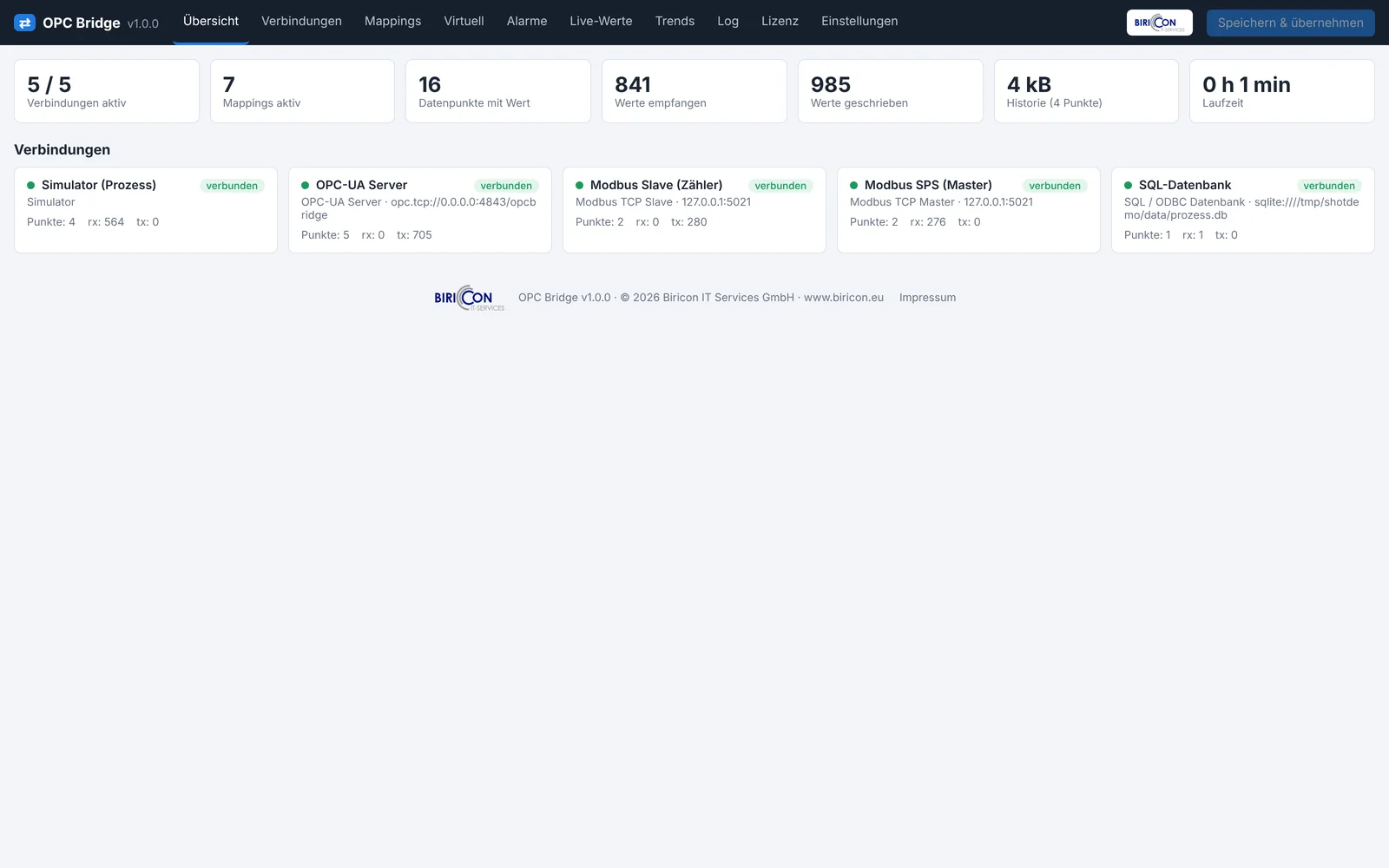
The overview shows the Bridge's health at a glance:
- Connections: number and state (connected/connecting/error/stopped), each shown with colour and status message.
- Mappings: number of active mappings.
- Store-and-forward: buffered values per target connection (if active).
- License: current status (licensed/demo/remaining time).
Values update in real time (see chapter 36).
12. Live Values tab
Here you see the current values of all monitored points in real time – with value, quality and timestamp.
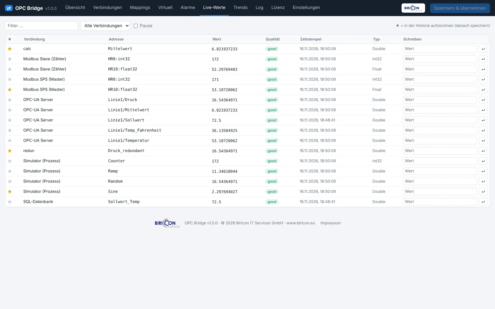
Functions:
- Pause: freezes the display (data transfer continues in the background).
- Manual writing: for writable target points you can enter a value directly for testing and send it. Very useful during commissioning to exercise actuators or registers specifically.
- Filter/search: narrow points by name or connection.
»Tip« Use live values together with manual writing to test a new mapping chain before connecting the real source.
13. Trends tab
The trend shows historical values as a chart over time.
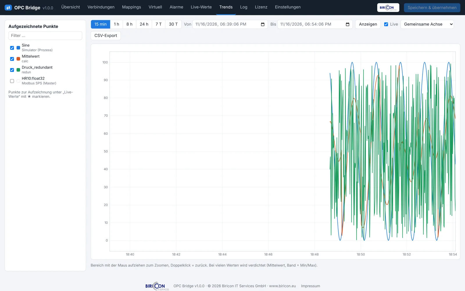
- Choose points: which recorded points are shown.
- Time range: e.g. last hour, last day, freely selectable.
- CSV export: download the displayed data as a CSV file (e.g. for Excel).
This requires the history to be enabled and the points selected for recording (chapter 30).
14. Log tab
The log shows operating messages of the Bridge: connections up and down, errors, warnings. It is the first place to look when problems occur.
- Messages are sorted by time and marked by severity.
- On connection errors the concrete cause is shown here (e.g. "timeout", "connection refused", "unknown address").
At system level the messages are additionally available in the Windows Event Log or, on Linux, via journalctl -u opcbridge.
Part IV – Configuration
15. Connections – general
In the Connections tab you create each link to a device or system.
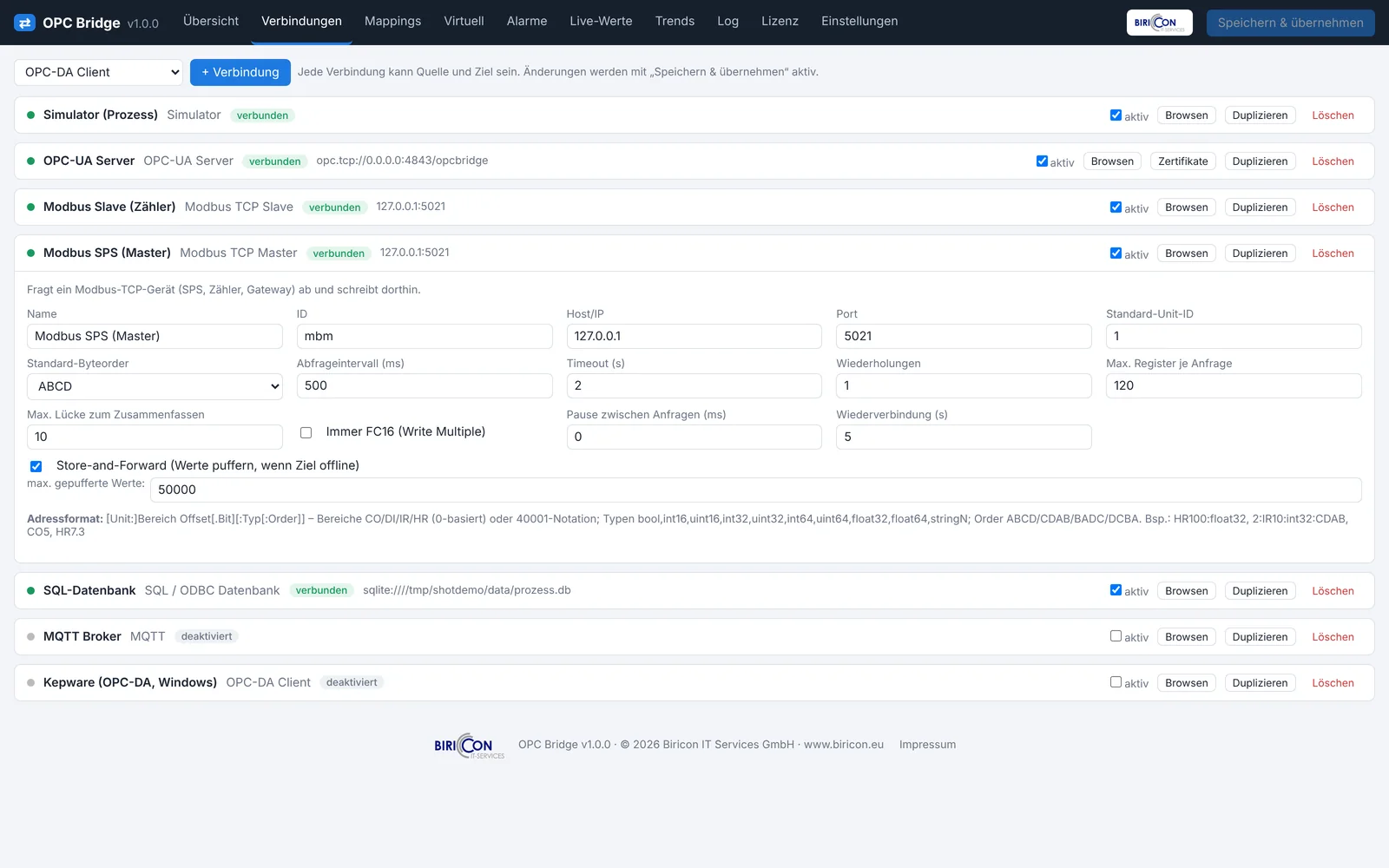
Creating a new connection:
- Choose the type (the protocol) from the list at the top.
- Click Add – a new card appears.
- Expand the card by clicking its header.
- Fill in the fields (each type shows exactly the fields it needs – see the following chapters).
- Save & apply.
Controls on each card:
| Element | Function |
|---|---|
| Name | free label (shown everywhere in the UI) |
| ID | technical identifier (automatic, referenced in addresses/mappings) |
| active | enables/disables the connection |
| Browse | search the device for available points (if the protocol allows) |
| Duplicate | create a copy of the card |
| Delete | remove the connection |
| Store-and-forward | enable buffering (chapter 29) |
The following chapters describe the fields per connection type in full. The Default column gives the default value.
16. Connection type OPC-DA
Role: client (reads/writes items of an OPC-DA server). Windows only.
| Field | Meaning | Default |
|---|---|---|
| Server ProgID | identifier of the DA server, e.g. Matrikon.OPC.Simulation | – |
| Host | hostname/IP for a remote server (empty = local, recommended) | empty |
| Update rate (ms) | how often items are read | 1000 |
| Read source | cache (server buffer, fast) or device (direct from device) | cache |
| Automation wrapper | path/ProgID of the OPC automation wrapper (if needed) | empty |
| Reconnect (s) | wait time before reconnecting | 10 |
| Query data type on browse | also determine the type when browsing | on |
Address format: Channel1.Device1.Tag1 (defined by the server; browsable).
»Caution« Remote access requires DCOM configuration. Recommendation: run the Bridge locally on the DA server machine.
17. Connection type OPC-UA Client
Role: client (reads/writes nodes of a foreign UA server, optional A&E).
| Field | Meaning | Default |
|---|---|---|
| Endpoint URL | address of the UA server, e.g. opc.tcp://192.168.0.10:4840 | opc.tcp://localhost:4840 |
| Security | security policy and mode (see 4.3) | None |
| User / Password | log in to the server (if required) | empty |
| Publishing interval (ms) | how often the server reports changes | 500 |
| Sampling interval (ms) | how often the server samples internally | 250 |
| Timeout (s) | timeout | 10 |
| Reconnect (s) | wait before retry | 10 |
| Subscribe Alarms & Events (A&E) | receive events from the server | off |
| Event source (NodeId) | source of events (default: server object i=2253) | i=2253 |
| Event type (NodeId) | event type to subscribe (i=2041 = BaseEventType) | i=2041 |
| Minimum severity (1–1000) | only events from this severity | 1 |
Address format: ns=2;s=Line1.Temp or ns=3;i=1001. Browsable.
18. Connection type OPC-UA Server
Role: server (provides its own values that others read/write).
| Field | Meaning | Default |
|---|---|---|
| Bind address | network interface (0.0.0.0 = all) | 0.0.0.0 |
| Port | UA port | 4840 |
| Endpoint path | path part of the endpoint URL | /opcbridge |
| Server name | displayed name | OPC Bridge |
| Namespace URI | identifier of the own namespace | urn:opcbridge |
| Root folder | optional parent folder in the address space | empty |
| Security policies | allowed policies (multiple) | None, Basic256Sha256 SignAndEncrypt |
| Client certificates | trust_all or truststore (only stored ones) | trust_all |
| Anonymous access | off / read / readwrite | read |
| Users | user list with permissions | – |
Addressing: the path Plant/Line1/Temperature you set on the target point is automatically turned into a NodeId ns=<idx>;s=Plant/Line1/Temperature.
»Caution« trust_all and anonymous=readwrite are only acceptable in protected networks. For production use a certificate truststore and users.
19. Connection type Modbus
There are four Modbus connection types: TCP Master, RTU Master, TCP Slave, RTU Slave.
19.1 Modbus TCP Master
| Field | Meaning | Default |
|---|---|---|
| Host/IP | address of the Modbus device | 192.168.0.10 |
| Port | TCP port | 502 |
| Default unit ID | device address (relevant with gateways) | 1 |
| Default byte order | default for multi-register values | ABCD |
| Poll interval (ms) | how often to read | 1000 |
| Timeout (s) | timeout | 2 |
| Retries | retries on error | 1 |
| Max registers per request | limits the block size | 120 |
| Max gap to combine | combines nearby registers into one request | 10 |
| Always FC16 (Write Multiple) | also write single values with function 16 | off |
| Delay between requests (ms) | relieves slow devices | 0 |
| Reconnect (s) | wait before retry | 5 |
19.2 Modbus RTU Master
Like TCP Master but over the serial line. Additional/differing fields:
| Field | Meaning | Default |
|---|---|---|
| Serial port | e.g. COM1 (Windows) or /dev/ttyUSB0 (Linux) | COM1 |
| Baud rate | 1200…115200 | 19200 |
| Parity | N/E/O (none/even/odd) | E |
| Data bits | 7 or 8 | 8 |
| Stop bits | 1 or 2 | 1 |
19.3 Modbus TCP Slave
| Field | Meaning | Default |
|---|---|---|
| Bind address | network interface | 0.0.0.0 |
| Port | TCP port | 502 |
| Default unit ID | own device address | 1 |
| Allowed unit IDs | additional accepted IDs (e.g. 1,2,5) | empty |
| Default byte order | default for multi-register values | ABCD |
19.4 Modbus RTU Slave
Like TCP Slave but serial (fields Serial port, Baud rate, Parity, Data bits, Stop bits as for the RTU master).
Address format (all Modbus types): [Unit:]Area Offset[.Bit][:Type[:ByteOrder]], e.g. HR100:float32:CDAB, 2:IR10:int32, CO5, HR7.3, 40001:uint16, HR200:string20.
20. Connection type MQTT
Role: publish/subscribe at an MQTT broker.
| Field | Meaning | Default |
|---|---|---|
| Broker | hostname/IP of the broker | localhost |
| Port | 1883 (plain) / 8883 (TLS) | 1883 |
| TLS | enable encryption | off |
| Do not verify TLS certificate | for self-signed certificates | off |
| CA file | path to the CA for certificate verification | empty |
| User / Password | broker login | empty |
| Client ID | unique identifier (empty = automatic) | empty |
| QoS | delivery guarantee 0/1/2 | 0 |
| Retain on publish | keep last value in the broker | on |
| Payload format (publish) | raw (value only) or json | raw |
| Topic prefix | prepended to all topics | empty |
| Browse filter | topic filter when browsing (# = all) | # |
| Reconnect (s) | wait before retry | 5 |
Address format: hall1/temp; extract a JSON value with sensor/abc@data.temperature.
21. Connection type Sparkplug B
Role: Sparkplug B edge node (UNS) at an MQTT broker.
| Field | Meaning | Default |
|---|---|---|
| Broker / Port | MQTT broker (often TLS on 8883) | localhost / 1883 |
| TLS / Do not verify TLS certificate | encryption | off |
| User / Password | broker login | empty |
| Group ID | top level in the Sparkplug topic | Biricon |
| Edge Node ID | identifier of this edge node | Bridge1 |
| Device ID | optional device level under the node | empty |
| Use aliases | alias compression (recommended) | on |
| QoS | 0 or 1 | 0 |
| Reconnect (s) | wait before retry | 5 |
Address format: metric name, e.g. Temperature or Line3/Count.
22. Connection type CAN
Role: CAN gateway (signal extraction and/or raw transport).
| Field | Meaning | Default |
|---|---|---|
| Interface | socketcan / udp_multicast / slcan / pcan / kvaser / vector / seeedstudio / usb2can / virtual | socketcan |
| Channel | e.g. can0 (SocketCAN) or adapter channel | can0 |
| Bitrate (bit/s) | bus speed (must match the bus!) | 500000 |
| UDP port (udp_multicast) | port for CAN-over-Ethernet | 43113 |
| CAN-FD | extended frames with more data | off |
| Receive own transmissions | read back own frames | off |
| Cyclic transmit (ms) | send periodically (0 = off) | 0 |
| Reconnect (s) | wait before retry | 5 |
| Raw gateway to connection | ID of a second CAN connection for raw transport | empty |
| Gateway bidirectional | forward frames both ways | on |
| Signals | list of extracted signals (bit position, factor, offset …) | – |
Address format: signal name from the signal list (created via analyzer/DBC). See chapter 32.
23. Connection type SQL
Role: write values to a database and/or read from one.
| Field | Meaning | Default |
|---|---|---|
| Connection URL (SQLAlchemy) | e.g. postgresql://user:pw@host/db, mssql+pyodbc://…, sqlite:///path.db | sqlite:///opcbridge_data.db |
| Poll interval (ms) | how often to read | 2000 |
| Read mode | keyvalue (rows with addr/value), columns (columns as points), off | keyvalue |
| Read query (SELECT) | SQL for reading | SELECT addr, value FROM tags |
| Write statement | SQL with :addr, :value, :ts | INSERT INTO tags(addr, value, ts) VALUES (:addr, :value, :ts) |
| Write only on change | saves write accesses | on |
| Recycle connection after (s) | pool recycling | 1800 |
| Reconnect (s) | wait before retry | 5 |
24. Connection type Webhook
Role: send values via HTTP to a URL.
| Field | Meaning | Default |
|---|---|---|
| Target URL | endpoint | https://erp.example.com/api/opcbridge |
| HTTP method | POST / PUT / PATCH | POST |
| Authorization header | e.g. Bearer <token> | empty |
| Content-Type | MIME type of the body | application/json |
| JSON template | template with {addr} {value} {quality} {ts} {conn} {name} | see 4.10 |
| Verify TLS certificate | certificate verification | on |
| Timeout (s) | timeout | 10 |
| Retries per request | retries | 2 |
| Reachability check (s) | health-check interval | 10 |
Address format: free tag name (appears as {addr}).
25. Connection type Bridge-Link
Role: mirror values between two Bridge instances over an outbound TLS connection.
| Field | Meaning | Default |
|---|---|---|
| Role | client (OT side, outbound only) or server (DMZ/IT side) | client |
| Server URL (client) | client target, e.g. wss://dmz-host:8765 | wss://dmz-host:8765 |
| Bind address (server) | network interface of the server | 0.0.0.0 |
| Port (server) | server port | 8765 |
| Shared token | secret for both sides (must match) | empty |
| TLS (server) | encryption at the server | on |
| TLS certificate/key (server, PEM) | the server's certificate | empty |
| Do not verify TLS certificate (client) | for self-signed server certificates | off |
| Reconnect (s) | wait before retry | 5 |
Address format: free tag name; identical names on both sides are mirrored. See chapter 48 for an example.
26. Mappings and data flow
A mapping is the rule that defines which point is transferred to which.
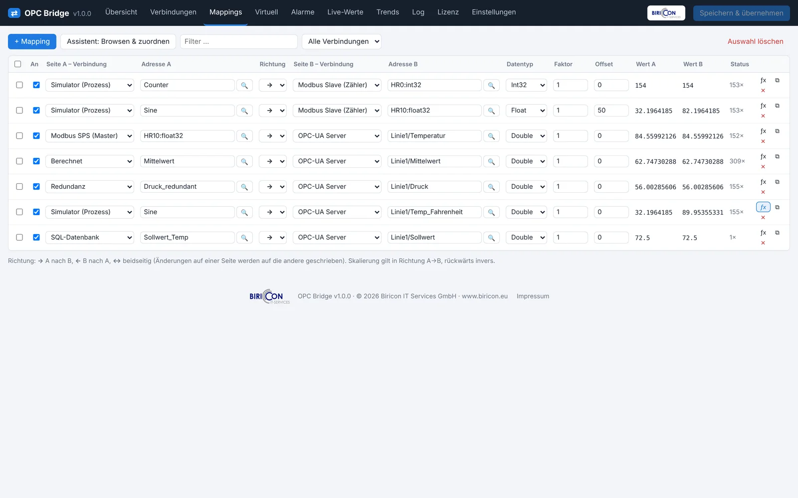
Creating a mapping:
- Mappings tab → Add.
- Choose source A: connection + address (browsable via the 🔍 button).
- Choose target B: connection + address.
- Set the direction:
- A → B: A is read and written to B.
- B → A: the reverse.
- A ↔ B: bidirectional; the most recently changed value is transferred.
- Optionally set data type and formula (chapter 27).
- Save & apply.
Field overview per mapping:
| Field | Meaning |
|---|---|
| A / B (connection + address) | the two endpoints |
| Direction | A→B, B→A, A↔B |
| Data type | target type (e.g. Double, Int32, Bool) |
| Formula | optional conversion (variable x) |
| active | enable/disable the mapping |
Multiple sources to one target / one point to many targets. You can use the same source point in several mappings (distributing to several targets) and route several sources to different targets. To merge several sources into one value, use virtual/computed points (chapter 28).
27. Conversion and formulas
Values often need conversion: units (°C↔°F), scaling (raw→percent), limiting. Each mapping can have a formula. The variable x represents the incoming value.
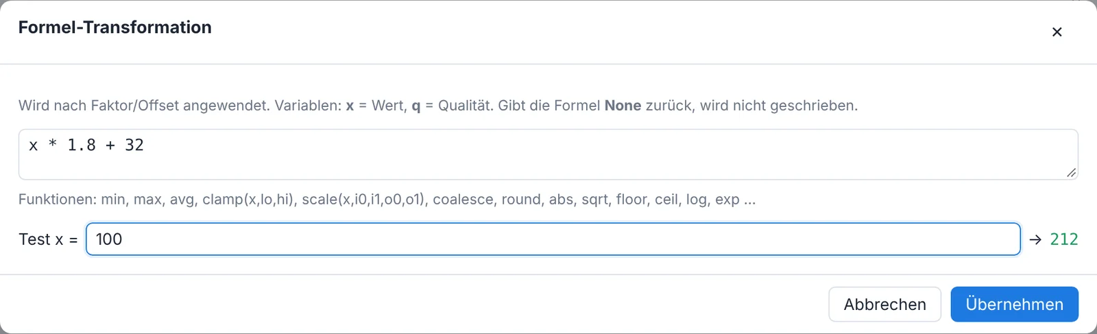
Examples:
| Purpose | Formula |
|---|---|
| °C → °F | x*1.8+32 |
| Scale /10 | x/10 |
| Raw 0–27648 → 0–100 % | scale(x, 0, 27648, 0, 100) |
| Limit to 0–100 | clamp(x, 0, 100) |
| Round | round(x, 1) |
| Threshold → bool | x > 50 |
A complete list of functions is in Appendix B.
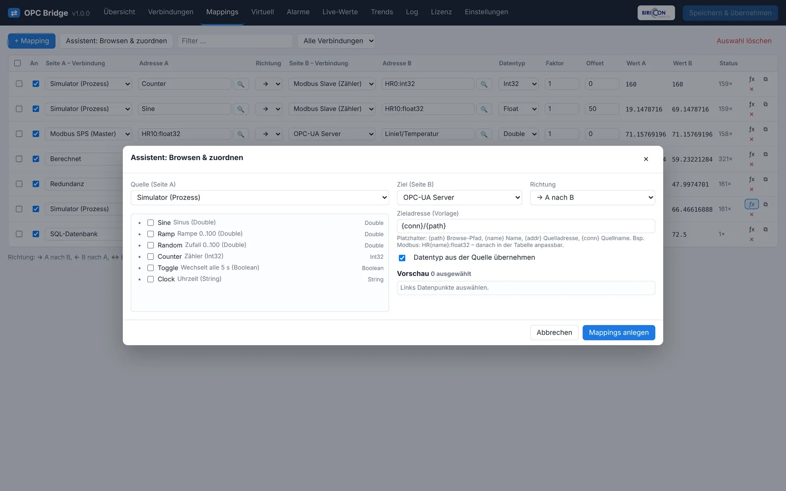
Wizard (bulk mapping). The browse wizard lets you search, select and map many points at once – ideal for large address spaces.
28. Virtual sources and redundancy
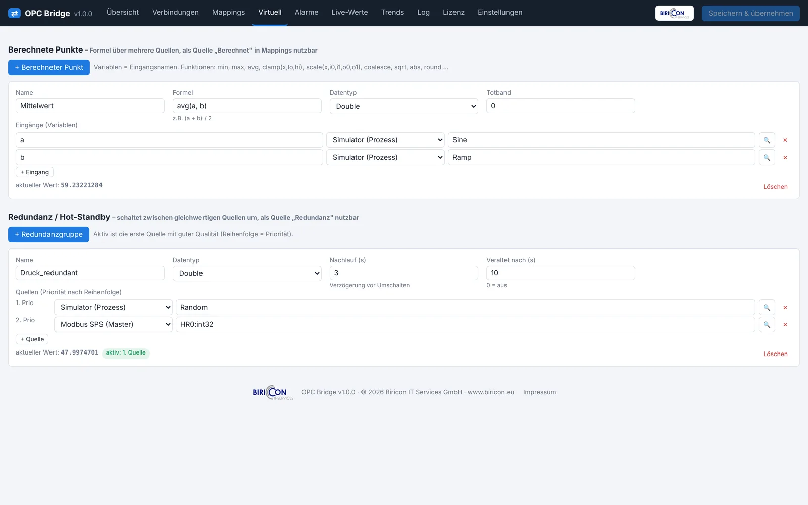
In the Virtual tab you create values that do not come directly from a device.
28.1 Computed points
A computed point is derived from several input points via a formula. Examples: average of three temperatures, sum of two counters, difference, minimum/maximum. The computed point is then usable like any other point in mappings, trends and alarms.
Create: assign a name, add inputs (connection+address), write the formula (inputs are available as variables), choose the data type.
28.2 Redundancy / hot-standby
A redundancy group has several sources for the same value. The Bridge automatically delivers the best available source and switches to the next on failure or bad quality (failover). Usable e.g. with redundant sensors or dually connected controllers.
Create: assign a name, add sources in priority order, set the criterion (e.g. quality, staleness).
29. Store-and-forward
Purpose. If a target is temporarily offline, values would be lost without buffering. With store-and-forward they are buffered persistently in an SQLite queue on disk – surviving even a restart of the Bridge – and delivered in correct order after reconnection.
Enable: on the target connection tick Store-and-forward and set the maximum buffer size (number of values). The overview and status show the number of buffered values per connection.
How it works:
- The target is detected as "error" (unreachable).
- Values to forward go into the queue (up to the maximum; then the oldest are dropped).
- As soon as the target is "connected" again, the queue is processed in order.
»Tip« Store-and-forward is especially important for cloud/webhook targets and the OT side of the Bridge-Link, where connections may drop temporarily.
30. Configuring history and trends
In Settings → History:
| Field | Meaning |
|---|---|
| History enabled | recording on/off |
| Retention (days) | how long data is kept |
| Min. interval per point (s) | throttling (prevents overly dense recording) |
| Database file | SQLite file of the history |
| Recorded points | list of points with optional deadband |
The deadband suppresses recording of small fluctuations (noise): only a change greater than the deadband is stored. Display is in the Trends tab (chapter 13) with CSV export.
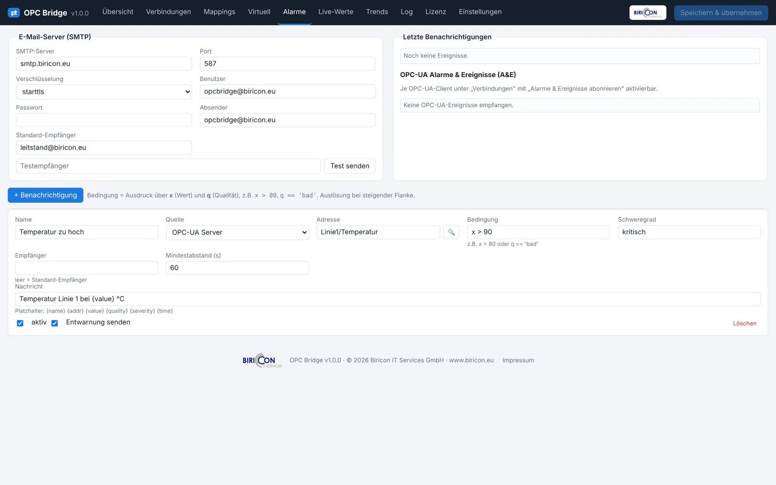
31. Alarms, e-mail and webhook
In the Alarms tab you define notification rules.
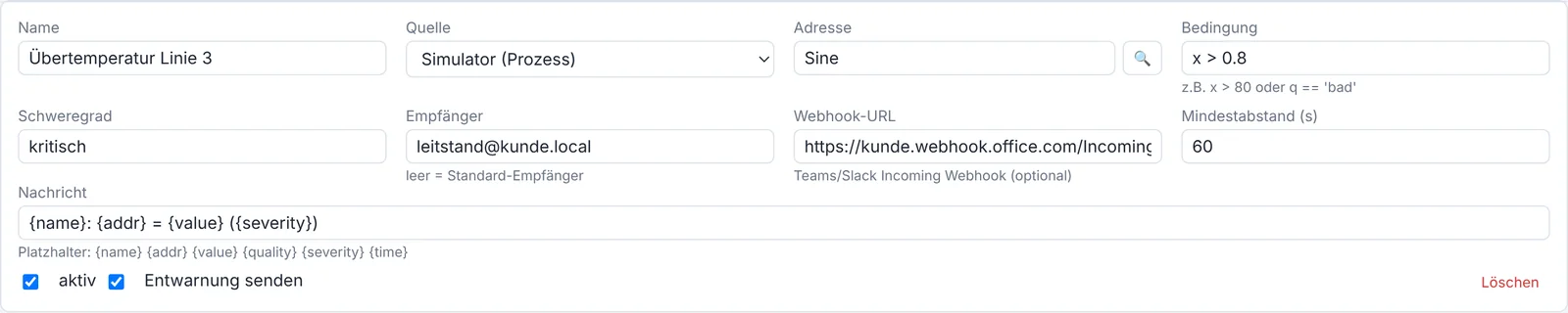
Fields of a rule:
| Field | Meaning |
|---|---|
| Name | label of the rule |
| Source / Address | the monitored point |
| Condition | expression over x (value) and q (quality), e.g. x > 90, q == 'bad' |
| Severity | e.g. Info/Warning/Critical |
| Recipient | e-mail address(es); empty = default recipient |
| Webhook URL | Microsoft Teams/Slack/generic incoming webhook (optional) |
| Minimum interval (s) | prevents alarm floods |
| Message | text with placeholders {name} {addr} {value} {quality} {severity} {time} |
| active | enable/disable |
| Send clear | message when the condition is no longer met |
Set up e-mail (SMTP): Settings → SMTP – host, port, TLS, user, sender, default recipient. SMS is possible via e-mail-to-SMS gateways.
Webhook: set an incoming webhook URL per rule (Teams/Slack). The alarm text is sent as JSON ({"text": …}).
OPC-UA Alarms & Events (A&E): events received from a server by the UA client also appear in the alarm area.
32. CAN analyzer and gateway
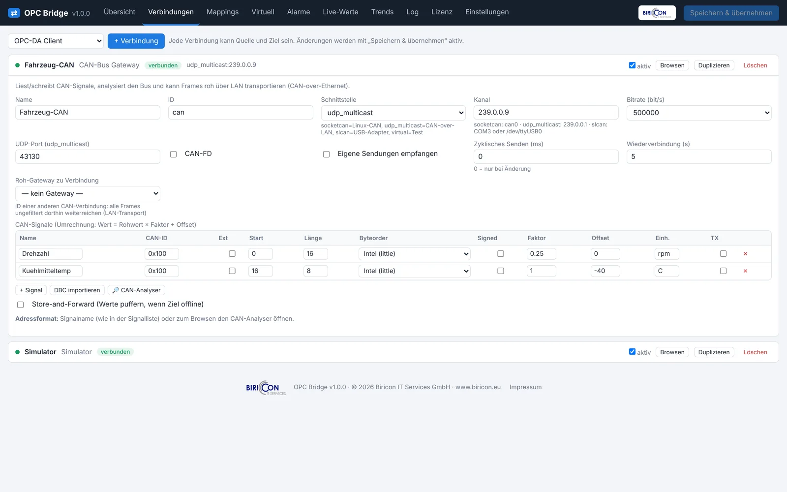
Finding signals (analyzer). The CAN analyzer shows the running frames in real time: ID, length, data bytes, frequency. For extended frames, J1939 information (PGN, SA, priority) is decoded automatically.
Creating signals. For each required signal you define:
| Parameter | Meaning |
|---|---|
| Name | label (= address in mappings) |
| CAN ID | message containing the signal |
| Start bit / length | bit position in the data field |
| Byte order | Intel (little) / Motorola (big) |
| Sign | signed/unsigned |
| Factor / Offset | physical value = raw · factor + offset |
Alternatively import the signal definitions via DBC import.
Raw gateway. Instead of extracting signals, the entire bus can be transported unfiltered over LAN (field Raw gateway to connection), coupling two remote CAN segments over Ethernet (optionally bidirectional).
Exporting values. Extracted signals are routed like any point via mapping to OPC, Modbus or MQTT – including conversion formulas.
33. Modbus register inspector
Modbus values are often cryptic: which register, which data type, which byte order? The register inspector reads a register range and shows all interpretations at once.
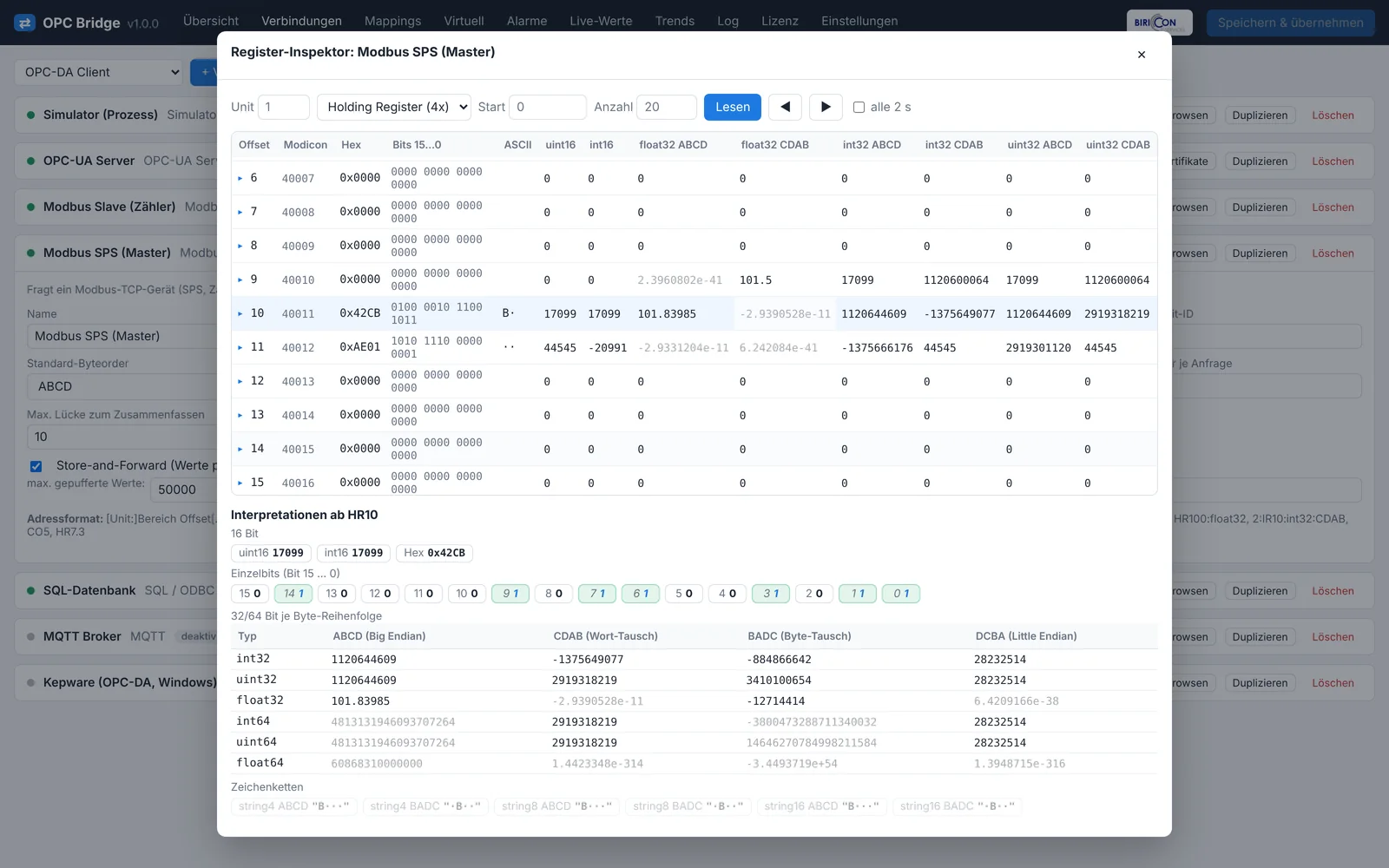
Procedure:
- Choose the Modbus connection, area (HR/IR), start address and count.
- The inspector reads and shows, per register pair, the interpretation as
int16,uint16,int32,uint32,float32– in all byte orders (ABCD,CDAB,BADC,DCBA). - The row with the plausible value reveals data type and byte order. Enter these into the address, e.g.
HR100:float32:CDAB.
»Tip« The register inspector saves a lot of time and guesswork during commissioning. Use it whenever a Modbus value is wrong.
34. WebView
The WebView is a public, token-protected live page (/view?token=…) that shows selected values as tiles – without login.
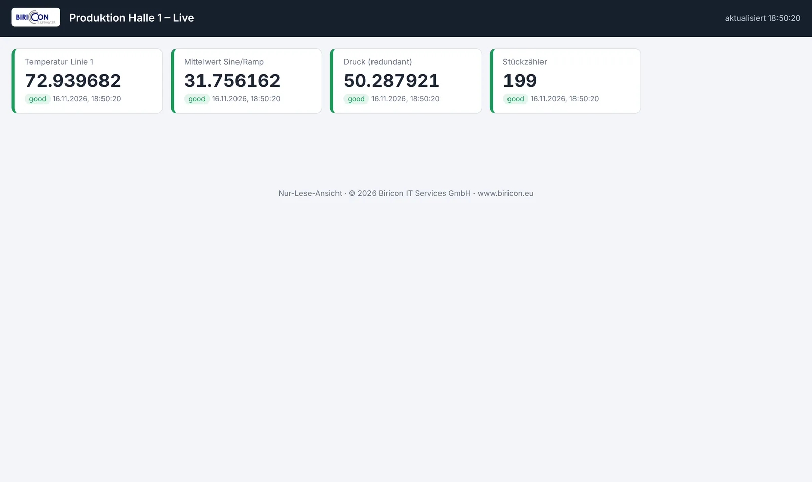
Set up: Settings → WebView – enable, assign a title, select points, set a token. The link can be shared with the control room or a customer.
| Field | Meaning |
|---|---|
| WebView enabled | function on/off |
| Title | page heading |
| Token | secret in the link (/view?token=…) |
| Points | which values are shown |
»Caution« Anyone with link+token sees the shared values. Share only the needed points and put HTTPS in front for internet operation.
35. Users, roles and API authentication
In the Settings tab.
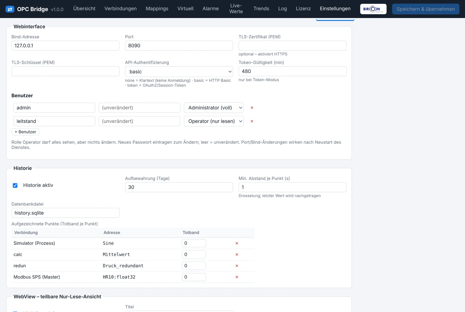
35.1 Users and roles
| Role | Permissions |
|---|---|
| Administrator | full access (read, configure, write) |
| Operator | read only – sees everything, changes nothing |
Passwords are stored as a PBKDF2 hash. Enter a new password to change it; empty = unchanged. Write accesses are restricted server-side to administrators.
35.2 API authentication (configurable)
| Mode | Meaning |
|---|---|
Plaintext (none) | no login – open access. Isolated machine network only! |
HTTP Basic (basic) | login like in the web interface. |
OAuth2/Session token (token) | login via /api/login or /api/token, then a Bearer token with a configurable lifetime (token TTL). |
35.3 Web interface settings
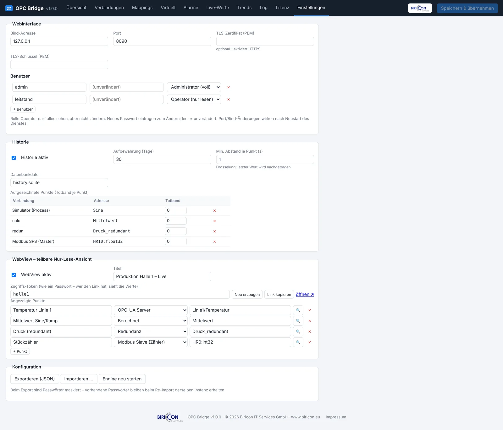
| Field | Meaning |
|---|---|
| Bind address / Port | network interface and port of the UI (takes effect after service restart) |
| TLS certificate / key (PEM) | enables HTTPS |
| API authentication | see 35.2 |
| Token lifetime (min) | token lifetime in token mode |
36. Real-time updates (WebSocket)
Live values and status are pushed in real time over WebSocket to the interface – without reloading, with minimal delay. If the WebSocket connection drops (e.g. due to a proxy), the interface automatically falls back to periodic polling and later retries the WebSocket.
Important for operation: the live update touches display cells only. Input and configuration fields remain operable at all times – an incoming update never overwrites your current input. You can configure in peace while live values arrive in the background.
Technically the WebSocket uses a short-lived ticket (via /api/wsticket) secured according to the chosen authentication mode.
36a. What's new in version 1.1
This chapter summarizes the additions in version 1.1. The features integrate seamlessly with the existing operation (schema-driven connection forms, mappings, store-and-forward, etc.).
36a.1 Siemens S7 driver (direct, without OPC-UA)
The new connection type Siemens S7 (direct) talks to S7-300/400/1200/1500 directly over RFC1006/ISO-on-TCP and reads/writes data blocks (DB), flags/merkers (M), inputs (I) and outputs (Q) – without OPC-UA having to be enabled or licensed on the PLC. In existing plants this is often the fastest way to connect an S7.
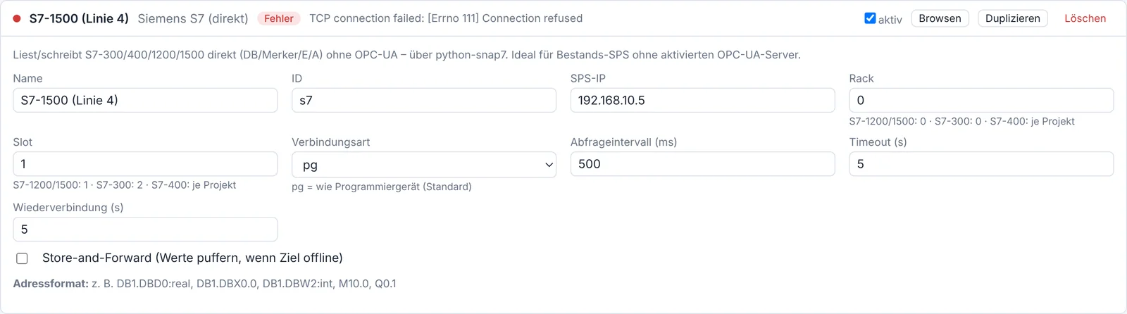
- Connection: PLC IP, rack and slot (S7-1200/1500: 0/1 · S7-300: 0/2).
- Address format:
DB1.DBX0.0(bool),DB1.DBW4(int),DB10.DBD20:real(real),DB1.DBD0:dint,M10.0,MW20,Q0.1, optional type suffix (:bool :int :dint :real :word :dword :string<n>). - Technology: requires the python-snap7 library (bundled in the package/image).
36a.2 InfluxDB time-series driver
The new output driver InfluxDB (time series) writes values in InfluxDB line protocol over HTTP – for InfluxDB v1 and v2/v3 – with batch writing for high throughput.
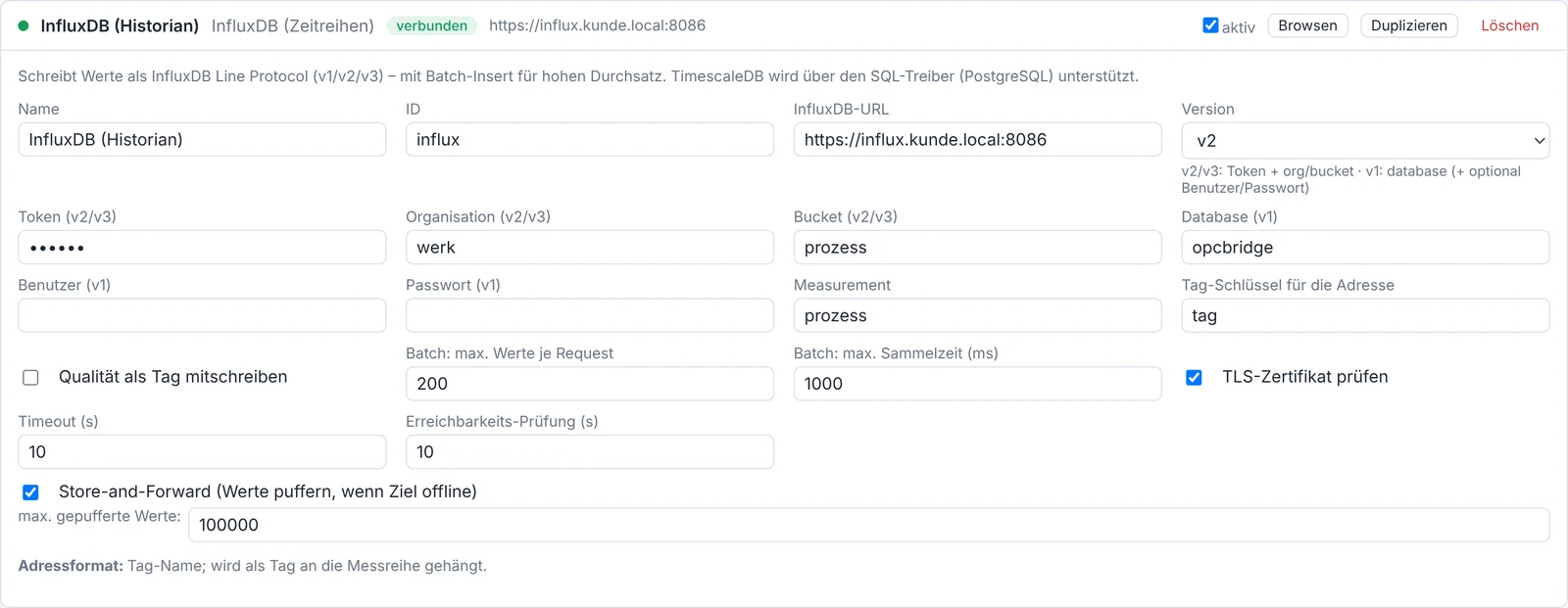
- v2/v3: token + organisation + bucket · v1: database (+ optional user/password).
- Measurement and tag key freely configurable; quality optionally as a tag.
- TimescaleDB is supported through the existing SQL driver (PostgreSQL URL).
36a.3 Batch/bulk writing (SQL, webhook, InfluxDB)
With many fast-changing tags, one request per value creates high overhead. The output drivers SQL, webhook and InfluxDB therefore offer a batch mode:
- Fields Batch: max values per request (0 = individual) and Batch: max collect time (ms).
- Data is sent once the count is reached or the collect time elapses.
- SQL writes a multi-row insert in one transaction, webhook a JSON array, InfluxDB a multi-line line protocol.
- Works optimally together with store-and-forward (buffered values are delivered in bundles).
36a.4 Strict one-way mode (data diode) in Bridge-Link
For critical-infrastructure and high-security environments, the Bridge-Link now offers a strict one-way mode (data diode): the return channel IT→OT is completely blocked.
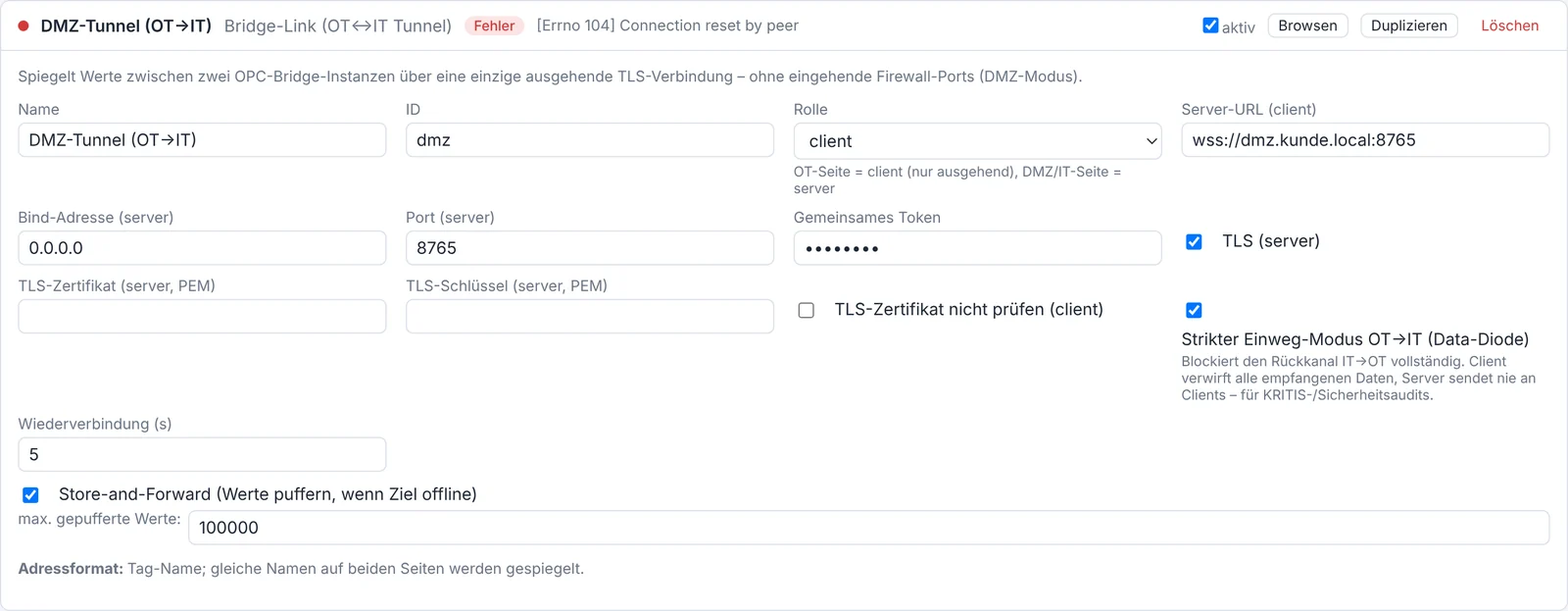
- Switch "Strict one-way OT→IT (data diode)" on the client and/or server side.
- The client (OT) then discards all received data, and the server (IT) never sends to clients – so the return channel is provably blocked on both sides.
- Ideal for security audits: values flow exclusively OT→IT.
36a.5 Central sign-in: LDAP/AD, OIDC/SSO and 2FA
For IT audits in larger operations, sign-in can now be connected to central user management and secured with two-factor.
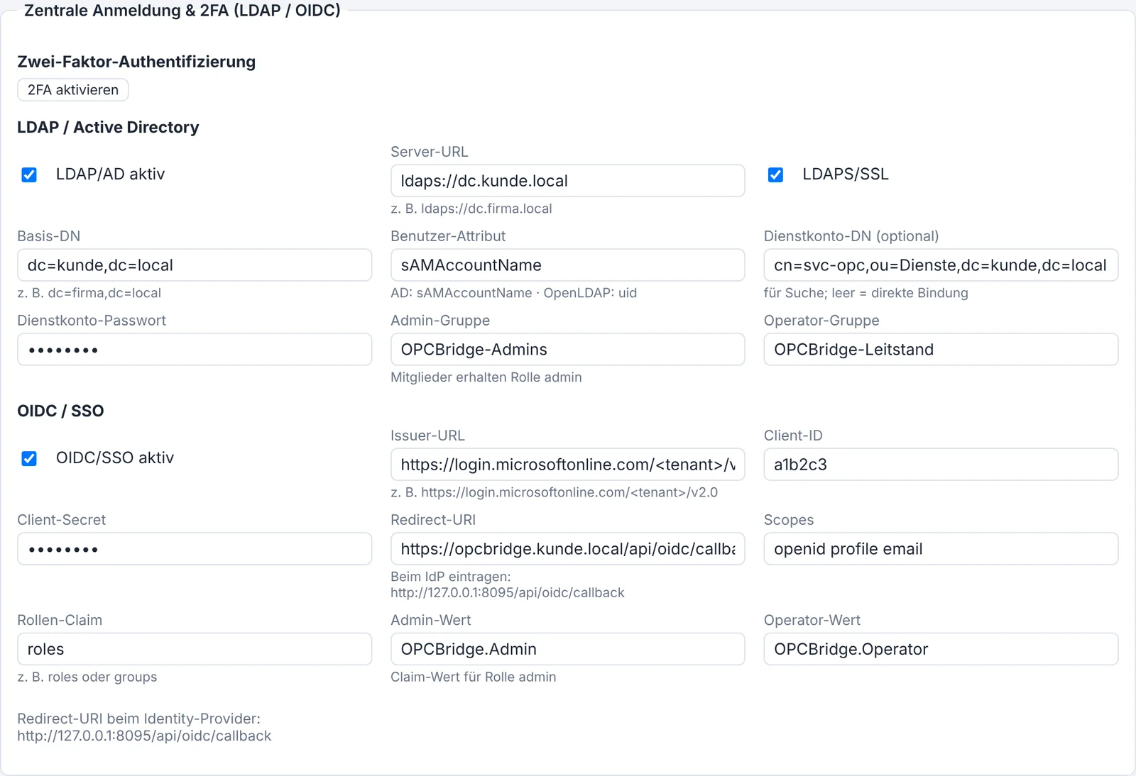
- LDAP / Active Directory: sign-in via directory service, group-to-role mapping (admin/operator group), service-account search or direct bind, LDAPS/SSL.
- OIDC / SSO: authorization-code flow (e.g. Microsoft Entra ID, Keycloak, Google). The "Sign in with SSO" button appears on the login; roles are derived from a claim. The redirect URI (
/api/oidc/callback) is registered at the identity provider. - TOTP 2FA: each local user can enable 2FA in settings (authenticator app via secret/QR). With 2FA active, the login additionally requires a 6-digit code; sign-in then uses token mode.
»Note« LDAP/OIDC/2FA are optional and disabled by default. Existing local users remain usable unchanged.
36a.6 Multilingual interface
The web interface is multilingual. The language selector at the top right switches between German, English, French, Spanish and Portuguese; the choice is stored in the browser.

German is the source language. If a translation is missing for a text, the German term is shown – so further translations can be added incrementally.
Part V – Interfaces and integration
37. REST API and built-in documentation
All functions of the Bridge are also available via a REST API – ideal for automation, custom dashboards or integration with supervisory systems.
Built-in interactive documentation. The API documentation is a fixed part of the product. You reach it at /api/docs. The complete interface is bundled and loads nothing from the internet (no CDN dependency) – so it works even in an air-gapped/OT network. It is based on the open OpenAPI 3.1 specification at /api/openapi.json. A ReDoc view is available at /api/redoc.
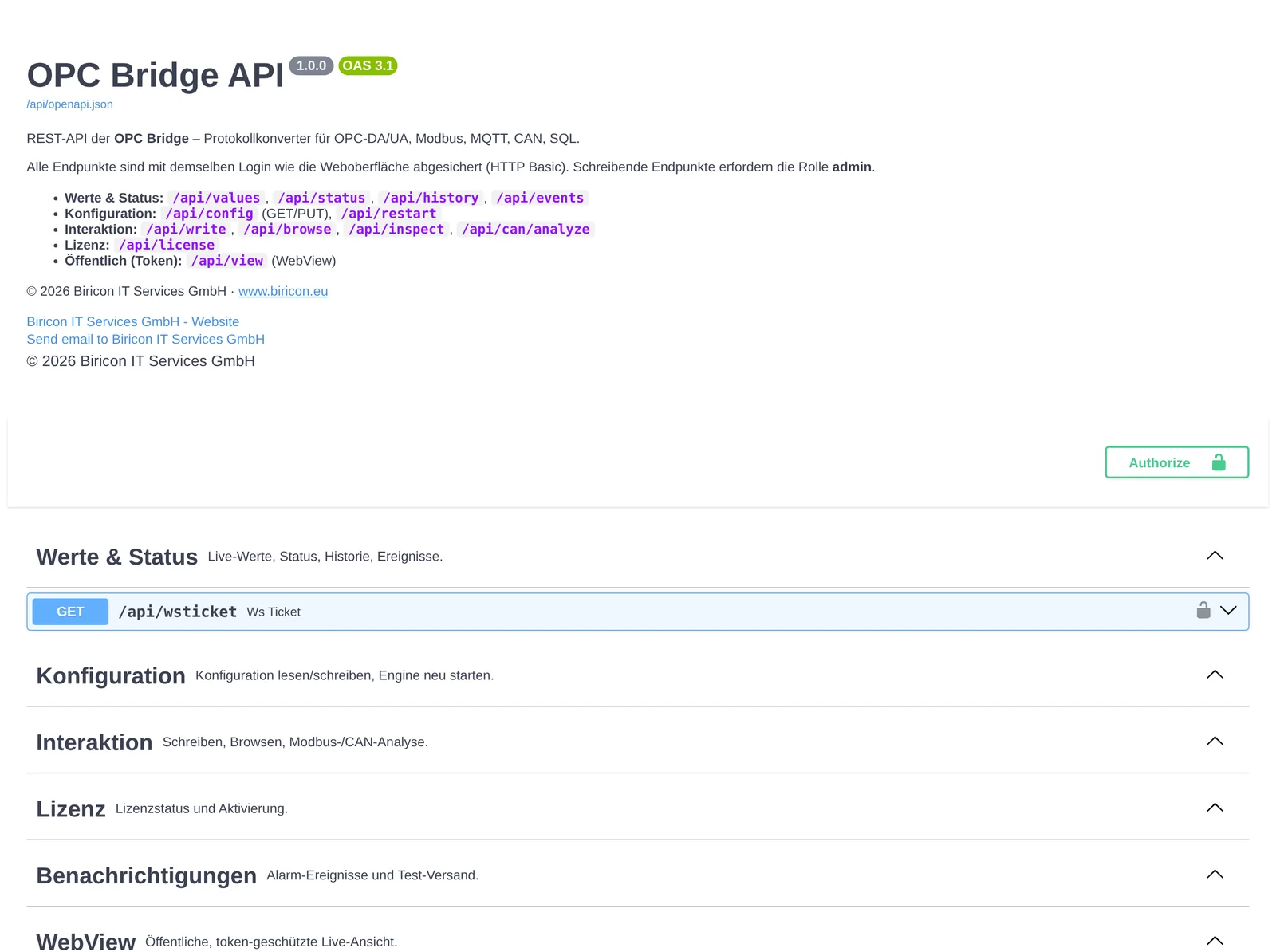
Every endpoint is testable directly in the interface ("Try it out"). A complete endpoint list is in Appendix C.
Authentication. Depending on the mode (chapter 35.2): none (plaintext), HTTP Basic or Bearer token. Example (obtain and use a token):
# Obtain a token (basic/token mode)
curl -u admin:secret -X POST http://host:8080/api/login
# -> {"token":"..."}

# Read values
curl -H "Authorization: Bearer <token>" http://host:8080/api/values
Writing endpoints (PUT /api/config, POST /api/write, POST /api/restart …) require the Administrator role.
38. Configuration file (config.json)
The entire configuration is stored in config.json in the data directory (see Appendix F). Normally you edit it via the interface; for backup, mass rollout or version control, direct access is useful.
Structure (simplified):
{
  "web":        { "host": "0.0.0.0", "port": 8080, "api_auth": "basic", "users": [ … ] },
  "history":    { "enabled": true, "retention_days": 30, "points": [ … ] },
  "connections":[ { "id": "sim", "type": "sim", "settings": { … } }, … ],
  "mappings":   [ { "a": {"conn":"…","addr":"…"}, "b": {"conn":"…","addr":"…"}, "dir":"a>b" }, … ],
  "computed":   [ … ], "redundancy": [ … ], "notifications": [ … ],
  "smtp":       { … }, "webview": { … }
}
»Caution« Passwords are stored hashed. Edit the file only with the service stopped, or load it via PUT /api/config. Invalid JSON prevents startup – always keep a backup (chapter 41).
Config as code. Because the entire configuration is in one file, it can be maintained in version control (e.g. Git) and rolled out to several plants.
Part VI – Operation and maintenance
39. Licensing
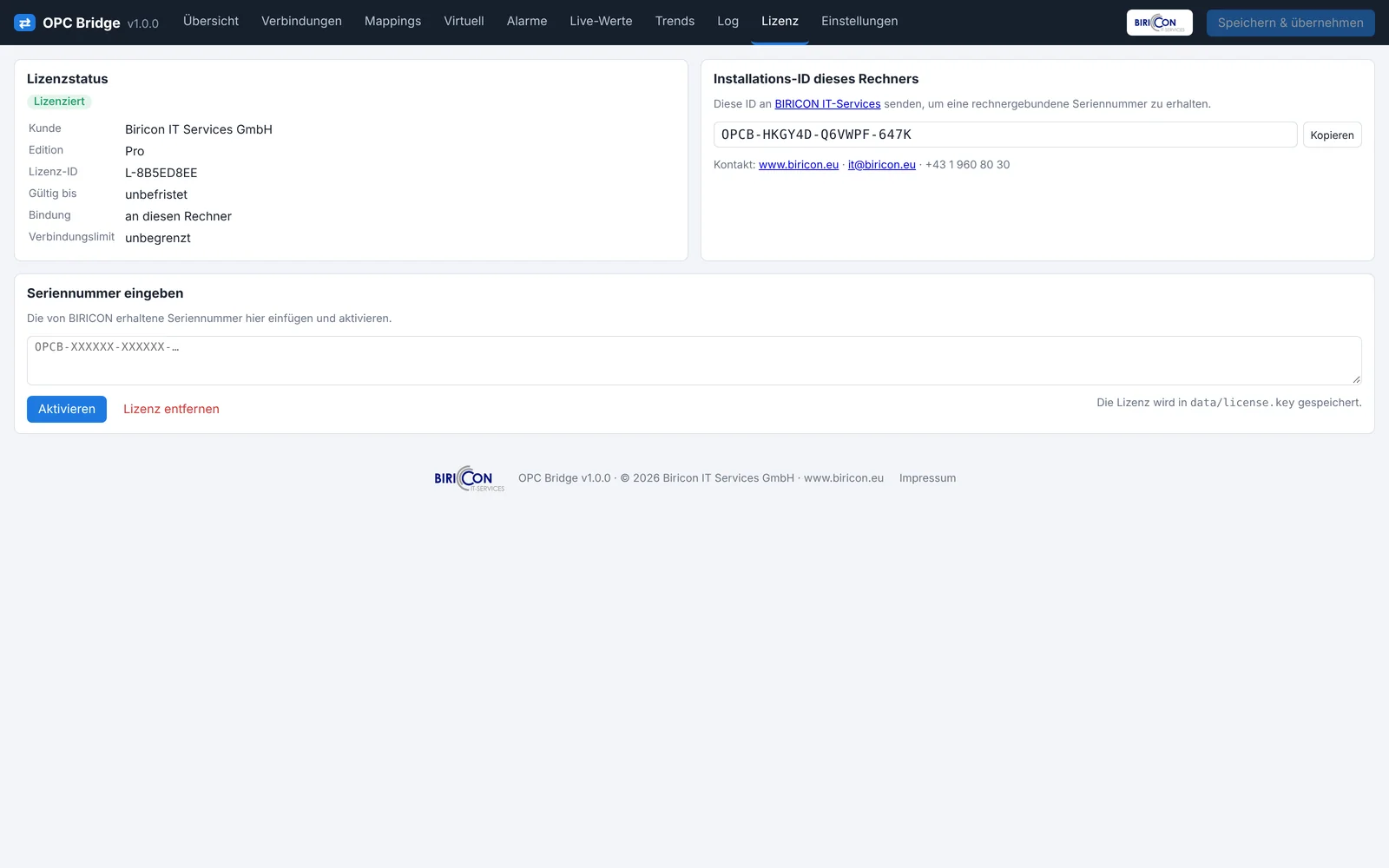
The OPC Bridge is protected by machine-bound serial numbers (Ed25519-signed, verifiable offline, tamper-proof).
39.1 Demo mode
Without a license the Bridge runs in demo mode:
- fully functional for 60 minutes per start, after which forwarding stops,
- permanently at most 2 connections.
A restart gives another 60 minutes – continuous operation requires a license.
39.2 Activation
- Open the License tab and read the installation ID (bound to this machine).
- Send the installation ID to Biricon.
- Enter the received serial number in the field and click Activate.
The license is valid for this exact machine. Hardware replacement requires re-issuing.
39.3 License types
- Perpetual: valid indefinitely.
- Time-limited (annual/maintenance): with an expiry date; renew in time.
40. Security and hardening
Recommendations for production:
- Change passwords. Change the initial password immediately; use strong passwords.
- Use roles. Give observers only the Operator role.
- API authentication at least Basic, better Token. Use Plaintext only in a physically isolated network.
- Enable HTTPS. Provide a TLS certificate/key or put a reverse proxy (nginx) with TLS in front.
- Secure OPC-UA. Policy
Basic256Sha256 SignAndEncrypt, truststore instead oftrust_all, users instead ofanonymous=readwrite. - Network segmentation. Separate OT and IT; use the Bridge-Link (DMZ mode) for the coupling so no inbound OT ports are needed.
- WebView only with a strong token and HTTPS; share only required points.
- Minimize ports. Enable only needed services (OPC-UA server, Modbus slave) and open only those in the firewall.
- Updates promptly (chapter 42).
41. Backup and restore
What to back up? The entire data directory (Appendix F) contains everything important:
config.json– the configuration,license.key– the license,- the history SQLite file (if the history should be backed up),
- the store-and-forward queue (only relevant with an active buffer).
Backup (Linux example):
sudo systemctl stop opcbridge
sudo tar czf opcbridge-backup-$(date +%F).tgz -C /var/lib opcbridge
sudo systemctl start opcbridge
Restore: stop the service, restore the data directory from the backup, start the service. Because the license is machine-bound, it works only on the same machine; on a new machine request a new license.
»Tip« For config-only backups, config.json suffices. Put it in version control to track changes.
42. Update and migration
Windows: run the new setup – it updates the program and keeps data and license. Back up the data directory beforehand.
Debian/Ubuntu:
sudo apt install ./opcbridge_<new-version>_amd64.debThe package updates the program; data under /var/lib/opcbridge/ is kept.
Docker: pull/build the new image and docker compose up -d – the volume ./data is kept.
Migration to another machine: copy the data directory, install the program – and request a new license (machine-bound).
43. Performance and sizing
- Poll intervals determine load: small
poll_ms/update_rate_msincrease freshness but also CPU and network load. Choose as slow as technically acceptable. - Modbus block building:
max_regsandmax_gapcombine registers into few requests – important for many registers and slow devices. - History: deadband and "min. interval per point" limit the data volume. Plan disk space according to retention and number of points.
- Many connections: each connection runs decoupled (multithreading); a slow peer does not slow the others.
- Network: for MQTT/Sparkplug/webhook over WAN, store-and-forward is strongly recommended.
44. Troubleshooting
The first place to look is always the Log tab, or on Linux journalctl -u opcbridge -f.
| Symptom | Possible cause | Solution |
|---|---|---|
| Cannot log in | password forgotten | initial password in initial_admin_password.txt (Appendix F). |
| Connection stays "connecting"/red | IP/port/firewall/device off | check address, port, network; read the error in the log. |
| Values are "bad" | source not delivering, wrong address | check address via browse; for Modbus use the register inspector. |
| Modbus number is nonsense | wrong type/byte order | register inspector → pick the right interpretation (e.g. :float32:CDAB). |
| OPC-DA unreachable | DCOM/bitness/Windows | run the Bridge locally on the DA server; check wrapper bitness. |
| OPC-UA "BadSecurityChecksFailed" | certificate not trusted | trust certificates mutually (truststore) or adjust the policy. |
| Change has no effect | not applied | click "Save & apply". |
| E-mail/webhook not arriving | wrong SMTP/URL | check SMTP data and webhook URL; test button; check the log. |
| Live values frozen | WebSocket blocked (proxy) | the UI falls back to polling; open proxy/firewall for WebSockets. |
| Sparkplug: node missing | host was offline before NBIRTH | request a Rebirth in the host (NCMD). |
| Bridge-Link not connecting | token/TLS/port/firewall | same token on both sides; open the OT side's outbound port; check the certificate. |
| CAN no frames | wrong bitrate/interface | match the bitrate to the bus; bring the SocketCAN interface up; check termination. |
| Demo stops after 60 min | no license | activate the license (chapter 39). |
| Service won't start (Linux) | startup error/invalid config.json | journalctl -u opcbridge -f; restore config.json from backup. |
Part VII – Application examples
45. Example: OPC-DA → OPC-UA
Goal: make values of a legacy OPC-DA controller available to a modern OPC-UA control system.
- Create the source: OPC-DA Client connection, enter the DA server ProgID (run the Bridge on the same machine).
- Create the target: OPC-UA Server connection, port 4840, security
Basic256Sha256 SignAndEncrypt. - Browse points: in the OPC-DA connection, browse the desired items.
- Mappings: one mapping per item DA.Item → UA path (e.g.
Plant/Line1/Temperature), direction A→B. Use the wizard for several at once. - Save & apply. The control system now connects as a UA client to
opc.tcp://<bridge>:4840/opcbridge.
46. Example: Modbus → MQTT cloud
Goal: a Modbus energy meter should send its measured values to an MQTT cloud.
- Source: Modbus TCP Master connection, meter host/IP, port 502.
- Identify values: use the register inspector to determine type and byte order (e.g.
HR100:float32:CDAB= active power). - Target: MQTT connection, broker address, TLS on, user/password, topic prefix
plant/meter1/. - Mappings:
HR100:float32:CDAB → power,HR102:float32:CDAB → energy, etc. - Store-and-forward enabled on the MQTT connection (WAN may drop).
- Save & apply.
47. Example: CAN → OPC-UA
Goal: provide the engine speed and temperature of a J1939 diesel generator as OPC-UA.
- Source: CAN connection, interface
socketcan, channelcan0, bitrate 250000. - Analyzer: read frames; identify the J1939 PGN (e.g. PGN 61444 for speed).
- Create signals:
Speed(start bit/length/factor 0.125) andCoolantTemp(factor 1, offset −40) – or via DBC import. - Target: OPC-UA Server connection.
- Mappings:
Speed → Generator/Engine/Speed,CoolantTemp → Generator/Engine/Temp. - Save & apply.
48. Example: OT→IT across the DMZ
Goal: bring process values from production (OT) into the IT zone without opening the OT firewall for inbound connections.
OT side (production network):
- Install the Bridge; connect the process sources (Modbus/OPC-UA/…).
- Bridge-Link connection, role client, server URL
wss://dmz-host:8765, set a shared token, enable store-and-forward. - Mappings: process points → Bridge-Link tags (same names as on the IT side).
IT/DMZ side:
- Install the Bridge.
- Bridge-Link connection, role server, port 8765, TLS with certificate, same token.
- Mappings: Bridge-Link tags → target (OPC-UA server for the control system, database, MQTT …).
Result: the OT side establishes the connection outbound only. No inbound port is needed in the OT firewall. Values flow mirrored into IT; on disconnection the OT side buffers.
Part VIII – Appendix
A. Address formats (complete)
| Connection | Format / examples |
|---|---|
| OPC-DA | Channel1.Device1.Tag1 |
| OPC-UA (client) | ns=2;s=Line1.Temp, ns=3;i=1001 |
| OPC-UA (server) | path Plant/Line1/Temperature → NodeId ns=<idx>;s=… |
| Siemens S7 | DB1.DBX0.0 (bool), DB1.DBW4 (int), DB10.DBD20:real, DB1.DBD0:dint, M10.0, MW20, Q0.1; type suffix :bool :int :dint :real :word :dword :string<n> |
| Modbus | [Unit:]Area Offset[.Bit][:Type[:ByteOrder]] — HR100:float32, 2:IR10:int32:CDAB, CO5, HR7.3, 40001:uint16, HR200:string20 |
| MQTT | hall1/temp; JSON path sensor/abc@data.temperature |
| Sparkplug B | metric name, e.g. Temperature, Line3/Count |
| SQL | column/key name; write statement with :addr, :value, :ts |
| InfluxDB | tag name (appended as a tag to the measurement) |
| CAN | signal name from the signal list (analyzer/DBC) |
| Webhook / Bridge-Link | free tag name |
Modbus areas: CO (coils), DI (discrete inputs), IR (input registers), HR (holding registers); 0-based or Modicon notation (0xxxx/1xxxx/3xxxx/4xxxx). Byte order: ABCD, CDAB, BADC, DCBA.
B. Formula and function reference
The variable x is the incoming value; for computed points the inputs are available as named variables.
| Category | Functions / operators |
|---|---|
| Arithmetic | +, -, *, /, % (modulo), ** (power) |
| Comparison/logic | >, <, >=, <=, ==, !=, and, or, not |
| Rounding | round(x, n), floor(x), ceil(x), int(x), abs(x) |
| Limit/scale | clamp(x, min, max), scale(x, in_min, in_max, out_min, out_max) |
| Min/max | min(a, b, …), max(a, b, …) |
| Math | sqrt(x), pow(x, y), log(x), exp(x), sin, cos, tan |
| Conditional | x if condition else y |
Examples: x*1.8+32, scale(x,0,27648,0,100), clamp(x,0,100), round(x,1), x if x>0 else 0.
»Note« For safety the formula interpreter is limited to mathematical expressions (no file access, no system calls).
C. REST endpoint reference
Base URL: http://<host>:8080. Interactive docs: /api/docs.
| Method | Path | Purpose |
|---|---|---|
| GET | /api/authinfo | query the auth mode (public) |
| POST | /api/login | log in (optional code for 2FA), obtain token |
| POST | /api/token | OAuth2 token (form) |
| POST | /api/logout | revoke token |
| GET/POST | /api/2fa/status, /api/2fa/setup, /api/2fa/enable, /api/2fa/disable | manage two-factor |
| GET | /api/oidc/start, /api/oidc/callback | OIDC/SSO sign-in |
| GET | /api/meta | product/version info |
| GET | /api/status | status of all connections/mappings |
| GET | /api/values | current values |
| GET | /api/history | history data (JSON) |
| GET | /api/history.csv | history as CSV |
| GET | /api/events | OPC-UA events |
| GET | /api/notifications | alarm events |
| POST | /api/notifications/test | send a test notification |
| GET/PUT | /api/config | read/write configuration (PUT: admin) |
| POST | /api/restart | restart the engine (admin) |
| POST | /api/browse | browse the address tree |
| POST | /api/write | write a value (admin) |
| POST | /api/inspect | Modbus register inspector |
| POST | /api/can/analyze | CAN analysis |
| POST | /api/can/dbc | DBC import (admin) |
| GET/POST/DELETE | /api/license | license status / activate / remove |
| GET | /api/wsticket | ticket for WebSocket |
| WS | /ws | real-time data stream |
| GET | /api/docs, /api/redoc, /api/openapi.json | API documentation |
| GET | /view, /api/view | WebView (token-protected) |
Writing endpoints require the Administrator role.
D. Data type reference
| Type | Description | Range | Modbus registers |
|---|---|---|---|
bool | truth value | true/false | 1 bit (CO/DI) or bit of a register |
int16 | 16-bit signed | −32768…32767 | 1 |
uint16 | 16-bit unsigned | 0…65535 | 1 |
int32 | 32-bit signed | ±2.1 bn | 2 |
uint32 | 32-bit unsigned | 0…4.29 bn | 2 |
int64 | 64-bit signed | very large | 4 |
float32 | 32-bit float (IEEE 754) | approx. ±3.4·10³⁸ | 2 |
double | 64-bit float | high precision | 4 |
string | text | depending on length | n (2 chars/register) |
E. Default ports
| Service | Port | Note |
|---|---|---|
| Web interface / REST | 8080 | configurable |
| OPC-UA server | 4840 | if enabled |
| Modbus slave | 502 | if enabled |
| MQTT (broker, peer) | 1883 / 8883 | 8883 = TLS |
| Bridge-Link | 8765 | DMZ server, configurable |
| InfluxDB (peer) | 8086 | v1/v2/v3 |
| Siemens S7 (peer) | 102 | RFC1006/ISO-on-TCP |
| CAN-over-Ethernet (UDP) | 43113 | with udp_multicast |
F. File and directory locations
| Platform | Data directory | Initial password |
|---|---|---|
| Windows | %ProgramData%\OPCBridge\ | …\initial_admin_password.txt |
| Linux (.deb) | /var/lib/opcbridge/ | …/initial_admin_password.txt |
| Docker | volume ./data | ./data/initial_admin_password.txt |
The data directory also holds: config.json (configuration), license.key (license), the history SQLite file and the persistent store-and-forward queue.
G. Commissioning checklist
- ☐ Bridge installed, service running, web interface reachable
- ☐ Initial password changed, operator user created if needed
- ☐ API authentication set appropriately (plaintext/basic/token)
- ☐ HTTPS enabled (production)
- ☐ Source connection(s) created and green
- ☐ Target connection(s) created and green
- ☐ For Modbus: type/byte order verified with the register inspector
- ☐ Mappings created, direction correct
- ☐ "Save & apply" clicked
- ☐ Live values checked (do values arrive?)
- ☐ Store-and-forward enabled on WAN/cloud targets
- ☐ History configured (if needed)
- ☐ Alarms set up and tested (e-mail/webhook)
- ☐ License activated (continuous operation)
- ☐ Backup of the data directory created
H. Glossary
| Term | Meaning |
|---|---|
| A&E | Alarms & Events – OPC-UA event messages |
| Byte order | order of bytes in multi-part numbers (ABCD/CDAB/BADC/DCBA) |
| DBC | description file for CAN signals |
| DMZ | isolated network zone between OT and IT |
| Edge node | data source at the plant edge (Sparkplug) |
| Engine | internal core executing mappings |
| Mapping | rule "value A → value B" |
| Master/Slave | Modbus roles (poll / provide) |
| OT/IT | production network / enterprise network |
| PGN/SA | Parameter Group Number / Source Address (J1939) |
| Publish/Subscribe | MQTT principle (publish/subscribe) |
| Quality | goodness of a value (good/uncertain/bad) |
| Store-and-forward | buffering on target failure |
| Tag/Point | a single value |
| UNS | Unified Namespace (consistent data structure over Sparkplug) |
I. Frequently asked questions (FAQ)
Must the browser stay open for data to flow? No. The Bridge runs as a background service. The browser is only for operation.
Can a value go in both directions? Yes, with direction A↔B. The most recently changed value is transferred.
What happens when the target connection drops? Without store-and-forward values are lost; with S&F they are buffered and delivered later.
Why does my Modbus value show nonsense? Almost always a wrong data type or byte order – check with the register inspector.
Do I need the internet for the API documentation? No. The documentation is fully bundled and works offline.
Does OPC-DA run on Linux? No, OPC-DA requires Windows. All other protocols run cross-platform.
How do I bring values securely from production into IT? Use the Bridge-Link in DMZ mode – outbound connection only, no inbound OT port.
How do I back up the configuration? Back up the data directory (at least config.json), see chapter 41.
OPC Bridge – Technical Operations Manual · Manual as of November 2026 · including what is new in version 1.1 · © 2026 Biricon IT Services GmbH. All trademarks are the property of their respective owners. Subject to technical changes.